Hyundai Accent: Brake System (ABS/ESC) / Parking Brake System
Components and Components Location
[Disc Type]
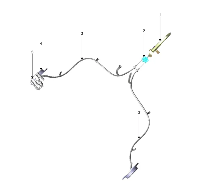
1. Parking brake lever
2. Equalizer assembly
3. Parking brake cable
4. Brake disc
5. Brake caliper
[Drum Type]
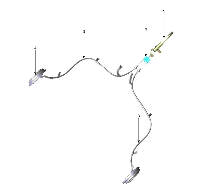
1. Parking brake lever
2. Equalizer assembly
3. Parking brake cable
4. Drum brake
Parking Brake Lever
1.Disconnect the negative (-) battery cable.
2.Release the parking brake.
3.Remove the floor console assembly.(Refer to Body - "Floor Console")
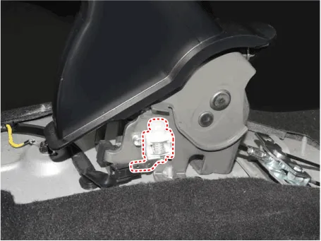
4.Disconnect the connector of parking brake switch.

5.Remove the parking brake switch.
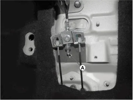
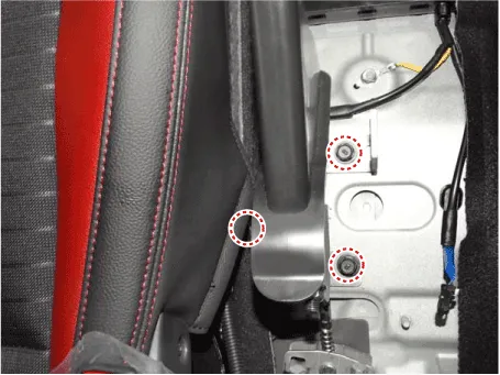
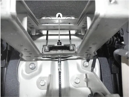
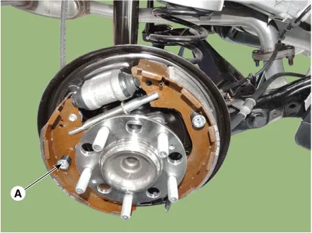
6.Remove the parking brake cable after loosening the nut (A).
7.Remove the parking brake lever assembly after loosening the bolts.
1.Install the parking brake lever assembly.
Tightening torque :19.6 - 29.4 N.m (2.0 - 3.0 kgf.m, 14.5 - 21.7 lb-ft)
Remove the parking brake lever assembly after loosening the bolts.

2.Install the parking brake cable.

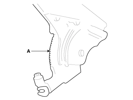
3.Apply a coating of the specified grease to each sliding parts (A) of the ratchet plate or the ratchet pawl.
Specified grease :CASMOLY 623
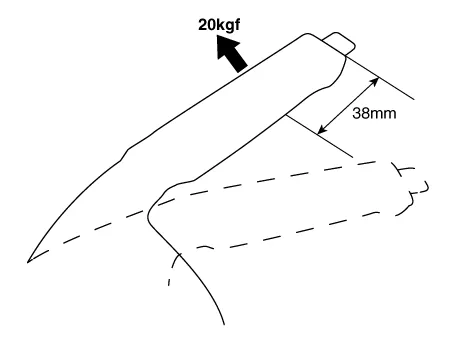
4.Install the parking brake cable adjuster, then adjust the parking brake lever stroke by turning adjusting nut (A).
Parking brake lever stroke :5 - 7 clicks (Pull the lever with 196N (20 kgf, 44 lbf))

1.Remove the floor console assembly. (Refer to Body - "Floor Console")
2.Bring the brake pads in their operating position by pressing the brake pedal down several times until there is resistance.
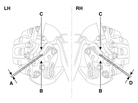
3.Tension the parking brake cable by tightening the adjusting nut, until the operating levers on both calipers lift from the stop, up to a distance of (A) and (D) between operating lever (B) and stopper (C).
Distance (A + D) : Max. 3 mm (0.12 in)
4.adjust the parking brake lever stroke by turning adjusting nut (A).
5.Release the parking brake lever fully, and check that parking brakes do not drag when the rear wheels are turned. Readjust if necessary.
6.Install the floor console. (Refer to Body - "Floor Console")
7.Make sure that the parking brakes are fully applied when the parking brake lever is pulled up fully.
Parking Brake Switch
1.Disconnect the negative (-) battery cable.
2.Release the parking brake.
3.Remove the floor console assembly. (Refer to Body - "Floor Console")
4.Disconnect the connector of parking brake switch.
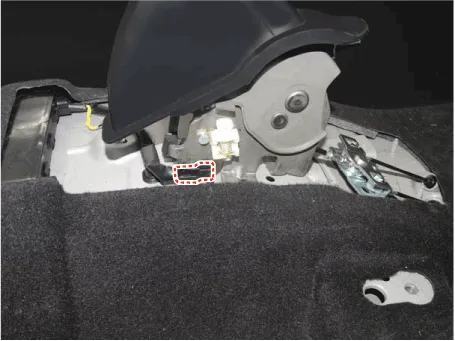
5.Remove the parking brake switch.

Parking Brake Cable ➤
Parking Brake Assembly
1.Loosen the wheel nuts slightly.Raise the vehicle, and make sure it is securely supported.
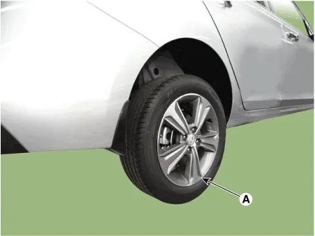
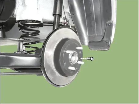
2.Remove the rear wheel and tire (A) from front hub.

• Be careful not to damage the hub bolts when removing the rear wheel and tire.
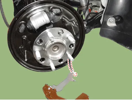
3.Loosen the screws and then remove the brake disc.

4.Remove the upper shoe return spring (A), lower shoe return spring (B), level pawl (C) and djuster assembly (D).
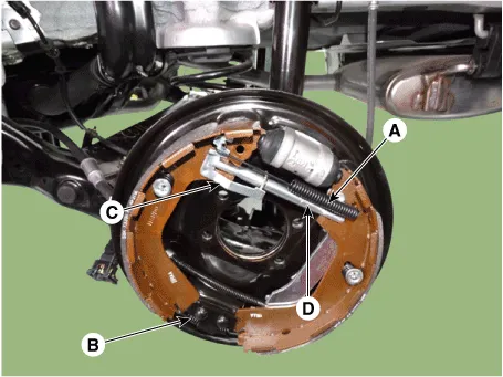
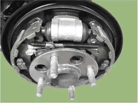
5.Remove the shoe hold assembly (A) and then remove the brake shoe.
6.Disconnect the parking cable.
7.To install, reverse the removal procedure.
8.Adjust the rear brake shoe clearance.
9.Rotate the toothed wheel of adjuster by a screw driver until the disc is not moving, and then return it by 5~7 notches in the opposite direction.
10.Instll the drum.
Tightening torque :4.9 - 5.9 N.m (0.5 - 0.6 kgf.m, 3.6 - 4.3 lb-ft)
11.Install the rear wheel and tire (A).
Tightening torque :107.9 - 127.5 N.m (11.0 - 13.0 kgf.m, 79.6 - 94.0 lb-ft)


• Be careful not to damage the hub bolts when installing the rear wheel and tire.


Other information:
Hyundai Accent (HC) (2017 - 2022) Service Manual: Valve Body
- Specifications Indirect Control Solenoid Driven Pulley Control Valve (Secondary_VFS) / Drive Pulley Control Valve (Primary_VFS) / Line Pressure Control Valve (Line_VFS) ItemSpecification Control typeN/H (Normally High) Control pressure kpa (kgf/㎠, psi)0 - 956.14 ± 14.71 (0 - 9.75 ± 0.15, 0 - 138.68 ± 2.13) Current (mA)0 - 1.100 Coil resistance (Ω)5. - Schematic Diagram - Terminal Function NoTerminal function 1- 2C-CAN LOW 3C-CAN HIGH 4GND 5IGN1 6- 7- 8- - Inspection FCA function ON / OFF switch was included to USM (User Setting Menu) and the state of the factory is ON.When the IGN ON, maintain ON condition by default. And does not reflect the driver settings when next IGN ON.
Contents
- Components and Components Location
- Parking Brake Lever
- Parking Brake Switch
- Parking Brake Cable
- Parking Brake Assembly
Categories
- Manuals Home
- Hyundai Accent Owners Manual
- Hyundai Accent Service Manual
- New on site
- Most important about car