Hyundai Accent: Keyless Entry And Burglar Alarm / Repair procedures
1.Remove the front door trim.(Refer to Body - "Front Door Trim")
2.Remove the front door module.(Refer to Body - "Front Door Module")
3.Disconnect the connectors from the actuator.
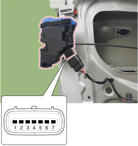
| No | Pin Information | |
| LH | RH | |
| 1 | Motor 1 | Lock / UnLock switch |
| 2 | Motor 2 | COM |
| 3 | - | Key Lock switch |
| 4 | Key Unlock switch | Key Unlock switch |
| 5 | Key Lock switch | - |
| 6 | COM | Motor 2 |
| 7 | Lock / UnLock switch | Motor 1 |
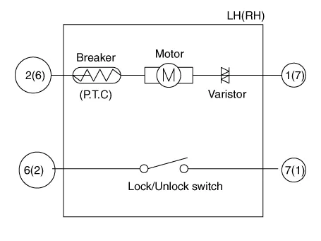
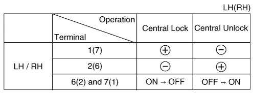
4.Check actuator operation by connecting power and ground according to the table. To prevent damage to the actuator, apply battery voltage only momentarily.
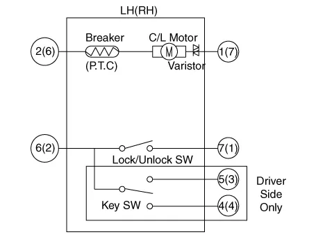
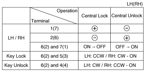
1.Remove the rear door trim.(Refer to Body - "Rear Door Trim")
2.Remove the rear latch.(Refer to Body - "Rear Door Latch")
3.Disconnect the connectors from the actuator.
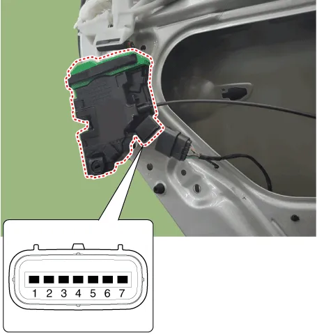
| No | Pin Information | |
| LH | RH | |
| 1 | Motor 1 | Lock / UnLock switch |
| 2 | Motor 2 | COM |
| 3 | - | - |
| 4 | - | - |
| 5 | - | - |
| 6 | COM | Motor 2 |
| 7 | Lock / UnLock switch | Motor 1 |
4.Check actuator operation by connecting power and ground according to the table. To prevent damage to the actuator, apply battery voltage only momentarily.
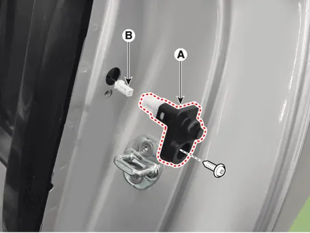
1.Remove the door switch (A) after loosening the screw and disconnecting the connector (B).
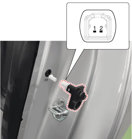
2.Check for continuity between the terminals in each switch position according to the table.

1.Remove the tailgate trim. (Refer to Body - "Tailgate Trim")
2.Disconnect the connector from the actuator.
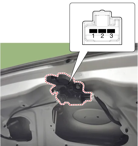
3.Check for continuity between the terminals in each switch position according to the table.

4.Check actuator operation by connecting power and ground according to the table. To prevent damage to the actuator, apply battery voltage only momentarily.

1.Disconnect the connector (A) and bolts from the hood switch.
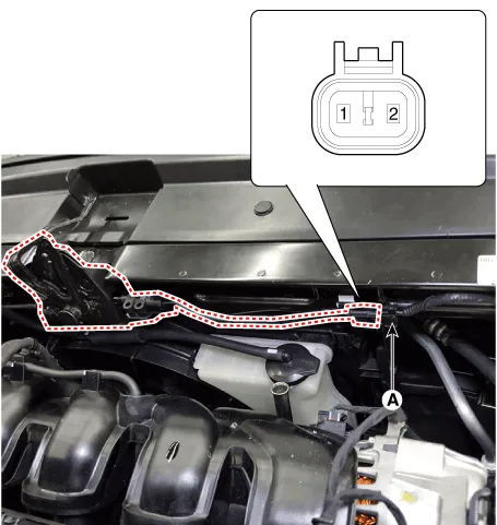
2.Check for continuity between the terminals and ground according to the table.

1.Remove the burglar horn (A) after removing a bolt and disconnecting the 2P connector from the burglar horn.
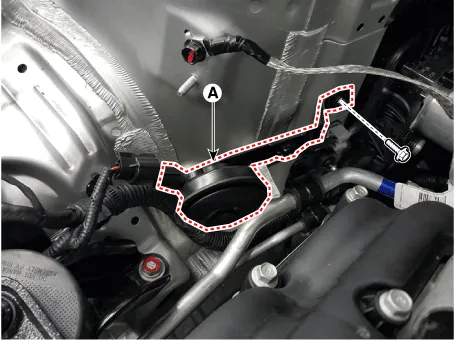
2.Test the burglar horn by connecting battery power to the terminal 1 and ground the terminal 2.
3.The burglar horn should sound. If the burglar horn fails to sound replace it.
Other information:
Hyundai Accent (HC) (2017 - 2022) Service Manual: Components and Components Location
- Components Connector Pin Information NoConnector AConnector BConnector CConnector DConnector 1Battery (+)Front wiper low backup switch inputStatic bending light (Left)_output-Dedicated DRL output 2RPAS power_outputRear washer switch imput-Key Interlock switch inputTail lamp relay output 3Ignition 1Rear wiper switch inputB-CAN (High)-Power window relay output 4Key IN switchFront wiper switch inputB-CAN (Low)-Front fog lamp relay output 5-Front wiper intermittent volume inputAuto ligHyundai Accent (HC) (2017 - 2022) Service Manual: Front Hub / Knuckle
- Components 1. Brake disc2. Front hub3. Hub bearing4. Dust cover5. Front axle6. Snap ring - Removal 1.Loosen the wheel nuts slightly.Raise the vehicle, and make sure it is securely supported. 2.Remove the front wheel and tire (A) from the front hub.Tightening torque :107.9 - 127.5 N.m (11.0 - 13.0 kgf.m, 79.6 - 94.0 lb-ft) • Be careful not to damage the hub bolts when removing the front wheel and tire.
Categories
- Manuals Home
- Hyundai Accent Owners Manual
- Hyundai Accent Service Manual
- New on site
- Most important about car


