Hyundai Accent: Clutch System / Clutch System
Clutch Cover And Disc
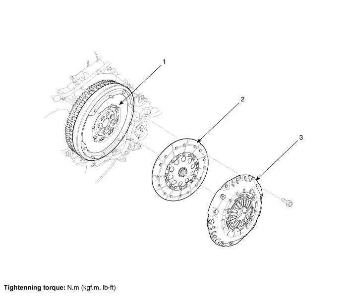
1. Engine flywheel
2. Clutch disc
3. Clutch cover
1.Remove the manual transaxle assembly.(Refer to Manual Transaxle System - "Manual Transaxle")
2. Remove the clutch cover assembly after loosening the bolts.

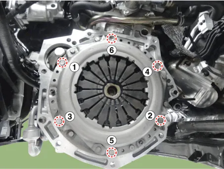
• Be careful not to be bent or twist bolts. Loosen bolts in diagonal directions.
1. Inspect diaphragm spring wear which is in contact with a concentric slave cylinder bearing.
2.Check the clutch cover and disc surface for wear or cracks.
3.Check the clutch disc lining for slipping or oil marks.
4.Measure the depth from a clutch lining surface to a rivet. If the measured value is less than the specification below, replace it.
Standard valueClutch disc thickness(A)[when free] : 8.3 ± 0.3 mm (0.3268 ± 0.0118 in.)Clutch disc rivet depth (B) : 1.1 - 1.6 mm (0.0433 - 0.0630 in.)Clutch disc rivet depth [Service Standard] : 0.3mm (0.0118 in.)
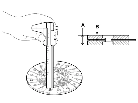

• If reinstalling used cover, the cover should be installed with its clutch disc as a set.
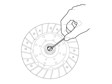
1.Apply grease on a disc spline part and transaxle input shaft spline part as required.
Specified grease : CASMOLY L9508Amount : 0.1 - 0.3g

• When not applying: Excessive wear of splines and bad clutch operation can occur.
• When excessively applying: Grease can be scattered bycentrifugal force which can conteminate the clutch disc. This can cause a loss of friction force causing a slip.
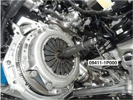
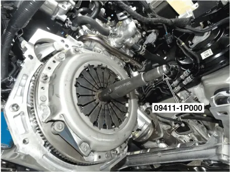
2.Install the clutch disc and the cover with SST (A: 09411-1P000).

• Transaxle shift error or a strangesound can occur due to clutch separation.
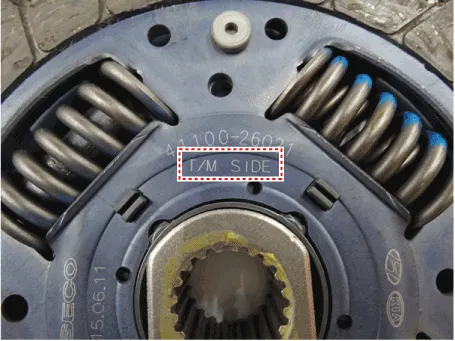
The 'T/M SIDE' marked surface should face the transaxle.
3.Install the clutch cover mounting bolts.
Tightening torque :14.7 - 21.6 N·m (1.5 - 2.2 kgf.m, 10.8 - 15.9 lb-ft)

• Install the all the components with the specified torques. If not, the clutch torque transaxle may have concerns or the mounting bolt can loosen.
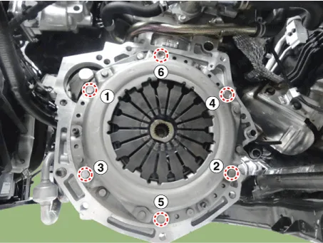
• When installing the clutch cover assembly, check the below fastening order for each number of bolts and tighten the bolts loosely. Then, fasten the bolts to their proper tightening torque. This can prevent twisting and vibration of the cover, and the lifting of the pressure plate. ㅡ Fastening order for each number of bolts for installing the clutch cover assembly
4.Remove the clutch disc guide SST (No.: 09411-1P000).
5.Install the transaxle assembly.(Refer to Manual Transaxle System - "Manual Transaxle")
Ignition Lock Switch ➤
Clutch Switch ➤
Clutch Pedal
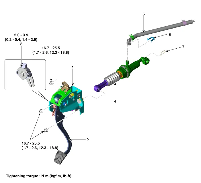
1. Clutch pedal assembly
2. Clutch pedal arm
3. Ignition & Clutch switch
4. Clutch master cylinder
5. Reservoir hose
6. Clip
7. Snap pin
1.Turn ignition switch OFF and disconnect the negative (-) battery cable.
2.Remove the clutch master cylinder.(Refer to Clutch System - "Clutch Matser Cylinder")
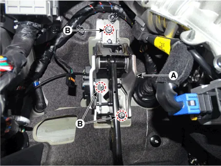
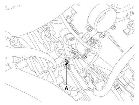
3.Disconnect the ignition lock & clutch switch connector (A).
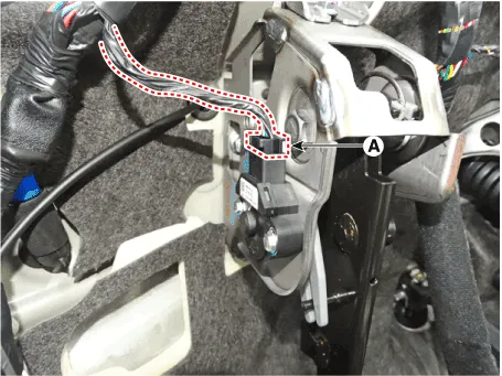
4.Remove the clutch pedal assembly (A) after loosening the bolts (B).
Tightening torque :16.7 - 25.5 N.m (1.7 - 2.6 kgf.m, 12.3 - 18.8 Ib-ft)
1.To install, reverse the removal procedures.
2.Perform bleeding air procedure in concecntric slave cylinder after pouring the brake fluid.(Refer to Concecntric Slave Cylinder - "Repair Procedures")
Clutch Tube
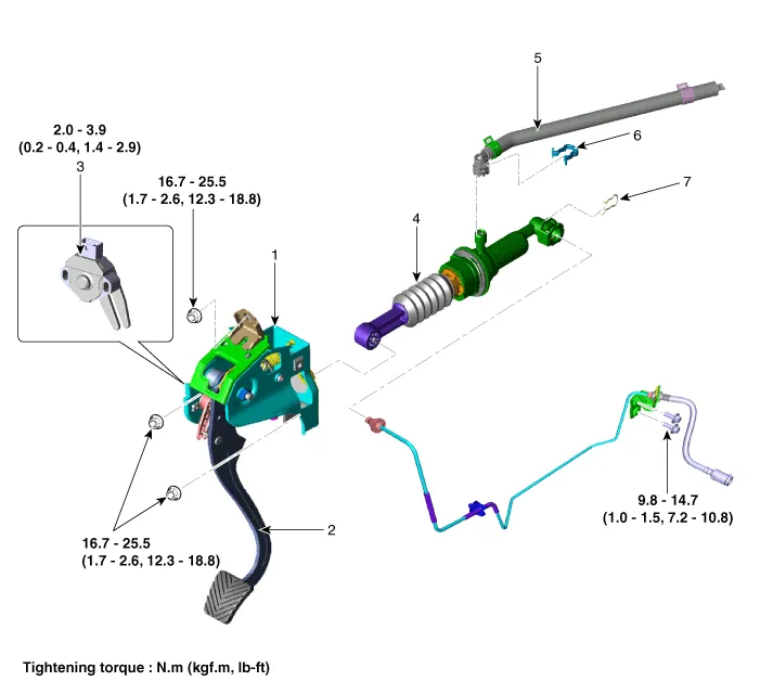
1. Clutch pedal assembly
2. Clutch pedal arm
3. Ignition & Clutch switch
4. Clutch master cylinder
5. Reservoir hose
6. Clip
7. Snap pin
8. Clutch tube & hose
1.Turn ignition switch OFF and disconnect the negative (-) battery cable.
2.Remove the air cleaner assembly and air duct.(Refer to Engine Mechanical System - "Air Cleaner")
3.Remove the battery and battery tray.(Refer to Engine Electrical System - "Battery")
4.Remove the engine control module (ECM).(Refer to Engine Control System - "ECM")
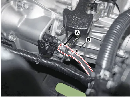
5.Remove the snap pin (A) and then separate the clutch tube (B).

• Do not spill brake fluid on the vehicle it may damage the paint if brake fluid does contact the paint, wash it off immediately with water.
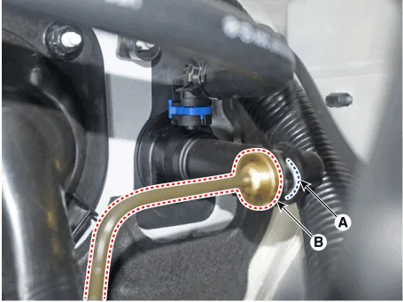
6.Loosen the clutch tube bracket bolts (A).
Tightening torque:9.8 - 14.7 N.m (1.0 - 1.5 kgf.m, 7.2 - 10.8 Ib-ft)
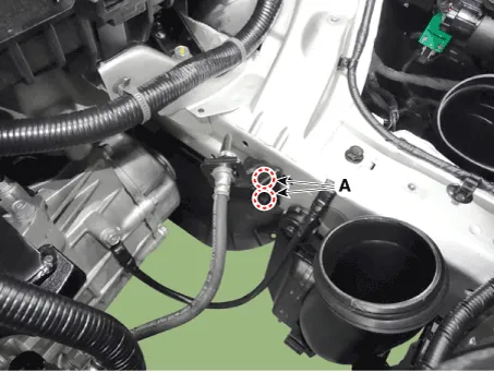
7.Remove the snap pin (A) and then separate the clutch hose & tube (B).
1.To install, reverse the removal procedures.
2.Perform bleeding air procedure in concecntric slave cylinder after pouring the brake fluid.(Refer to Concecntric Slave Cylinder - "Repair Procedures")
Clutch Master Cylinder
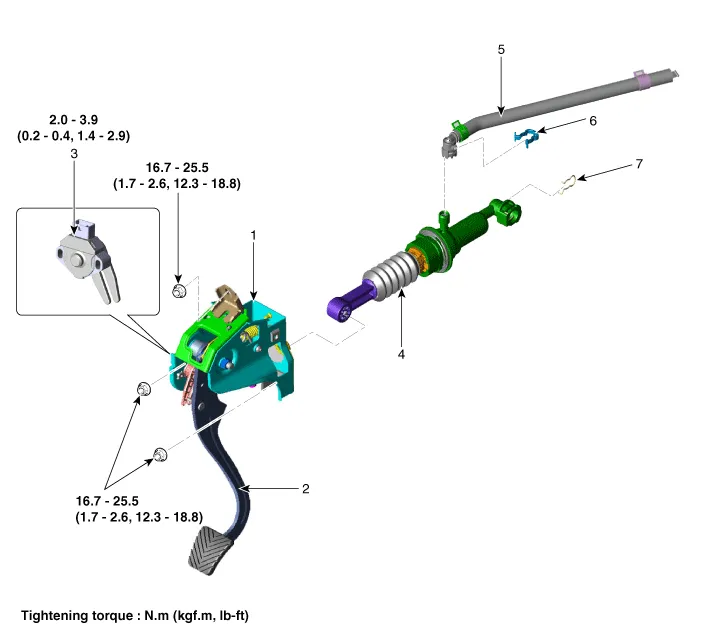
1. Clutch pedal assembly
2. Clutch pedal arm
3. Ignition & Clutch switch
4. Clutch master cylinder
5. Reservoir hose
6. Clip
7. Snap pin
1.Separate the push rod (A) from the clutch pedal.
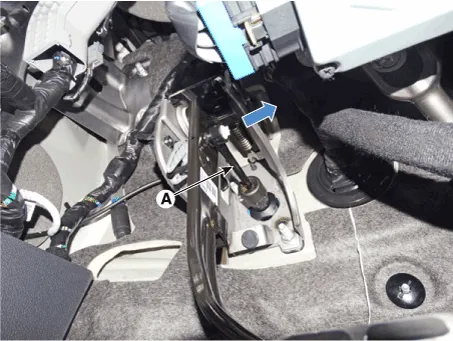
2.Turn ignition switch OFF and disconnect the negative (-) battery cable.
3. Remove the air cleaner assembly and air duct. (Refer to Engine Mechanical System - "Air Cleaner")
4.Remove the battery and battery tray.(Refer to Engine Electrical System - "Battery")
5.Remove the engine control module (ECM).(Refer to Engine Control System - "ECM")
6.Separate the reservoir hose and clutch tube.
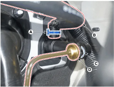
1)Remove the clip (A) and then separate the reservoir hose (B).
2)Remove the snap pin (C) and then separate the clutch tube (D).

• Do not spill brake fluid on the vehicle it may damage the paint if brake fluid does contact the paint, wash it off immediately with water.
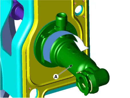
7. Remove the master cylinder (A) by turning it clockwise.
1.To install, reverse the removal procedures.
2.Perform bleeding air procedure in concecntric slave cylinder after pouring the brake fluid.(Refer to Concecntric Slave Cylinder - "Repair Procedures")
Concentric Slave Cylinder Assembly
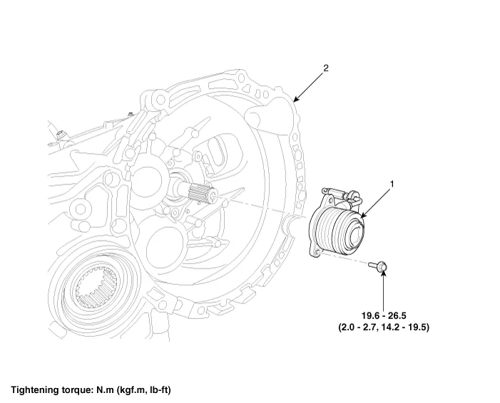
1. Concentric Slave Cylinder assembly (C.S.C)
2. Clutch housing
1.Remove the manual transaxle assembly. (Refer to Manual Transaxle System - "Manual Transaxle")
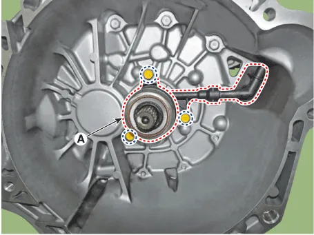
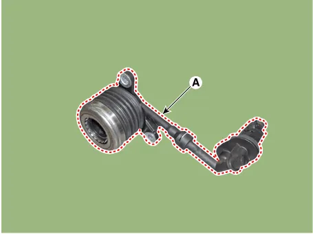
2.Loosen the bolts and then removing the concentric slave cylinder assembly (A) from the clutch housing.
Tightening torque :19.6 - 26.5 N.m (2.0 - 2.7 kgf.m, 14.2 - 19.5 lb-ft)
1.To install, reverse the removal procedures.

• Install the concentric slave cylinder bolts. Not to be bent or twisted, Tighten them in diagonal directions.
• Cup, Inner surface of body and outer surface of tube guide must be free from flaws.
• When it is assembled, it must be free from invasive foreign matters and oil leakage.

• When it is installed, assembly oil must be applied adequately to inner surface of body and outer surface of tube guide.
Specified fluid : KLUBER 9R1007
1.Turn ignition switch OFF and disconnect the negative (-) battery cable.
2.Remove the air cleaner assembly and air duct. (Refer to Engine Mechanical System - "Air Cleaner")
3.Open the concentric slave cylinder air bleed cap (A).
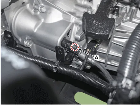
4.Connect the vinyl hose (A) to the air bleeder plug.
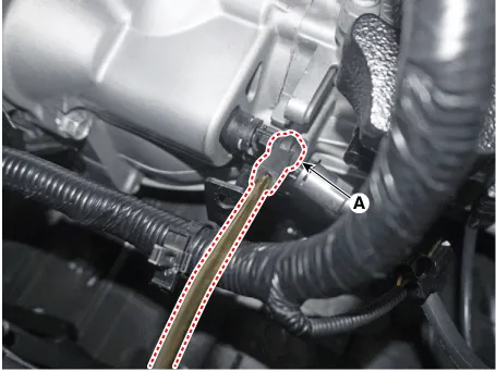
5.After opening the air bleeder plug (A), press and release the clutch pedal about 10 times.
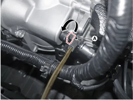

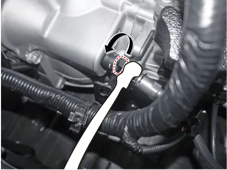
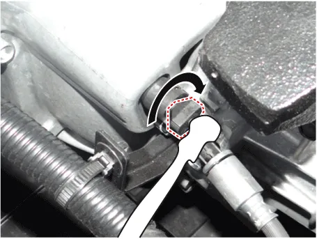
• How to open & close the air bleeder plug
| Open (Counter-Clockwise, 90˚) | Close (Clockwise, 90˚) |
|
|
Clutch Release Cylinder
1. Drain the brake fluid through the bleed plug (A).

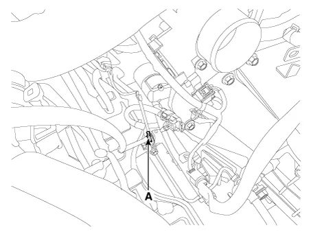
2. Loosen the release cylinder bolts (A) and then clutch tube nut (B) after removing release cylinder assembly ©.
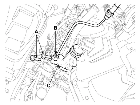
1. Install in the reverse order of removal.

Specified grease: TMG-3Quantity: 0.4 - 0.8 g
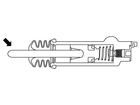
1. Check the clutch release cylinder for fluid leakage.
2. Check the clutch release cylinder boot for damage.

1. After disconnecting a cap from the clutch release cylinder air bleeder, insert a vinyl hose in the plug.
2. Refill the clutch master cylinder with the specified fluid.
Specified fluid: SAE J1703 (DOT 3 or DOT 4)
3. Loosening the plug screw, press and release the clutch pedal about 10 times.
4. Tighten the plug (A) during the clutch pedal pressed. Afterwards, raise the pedal with a hand.
5. After pressing the clutch pedal 3 times more, loosen the plug (A) and re-tighten it with the pedal pressed. Raise it again, then.
Tightening torque:7.8 - 13.7 N.m(0.8 - 1.4kgf.m, 5.8 - 10.1lb-ft)
6. Repeat the step 4 two or three times. (until there is no bubble in the fluid)
7. Refill the clutch master cylinder with the specified fluid.
Clutch Release Fork and Clutch Release Bearing

1. Clutch release fork
2. Clutch cover assembly
3. Clutch disk assembly
4. Clutch release bearing
1.Remove the transaxle assembly.(Refer to Manual Transaxle System - "Manual Transaxle")
2.Remove the clutch release bearing (A).
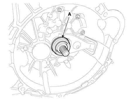
3.Pull the clip (A).
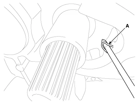
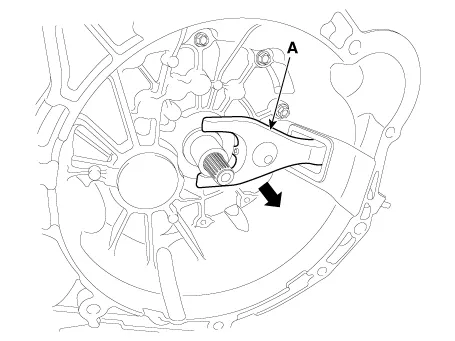
4.Remove the clutch release fork (A).
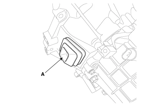
5.Remove the boot (A).
1.Check for damage to boot.
2.Check for deformation to clutch release fork.
3.Check for deformation to clutch release bearing.
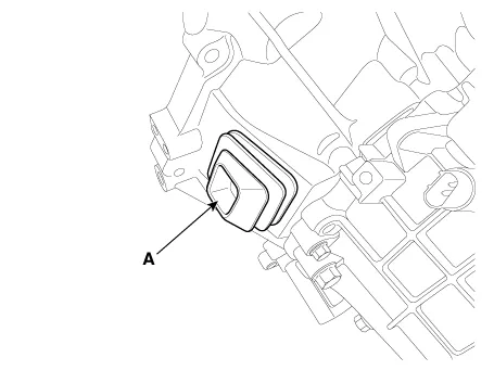
1.Install the boot (A).
2.Install the clip to the clutch release fork.
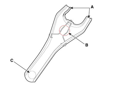
3.Apply to grease in location A, B and C.
| Location | Quantity (g) | Remarks |
| A | 0.3 - 0.5 | Release bearing & Fork |
| B | 0.5 - 1.0 | Release Fork & Fulcrum |
| C | 0.4 - 0.8 | Release cylinder & Fork |
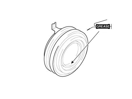
4.Apply the grease to the hole surface of the clutch release bearing all around.
Specified grease: CASMOLY L9508Amount: 0.5 - 0.7g
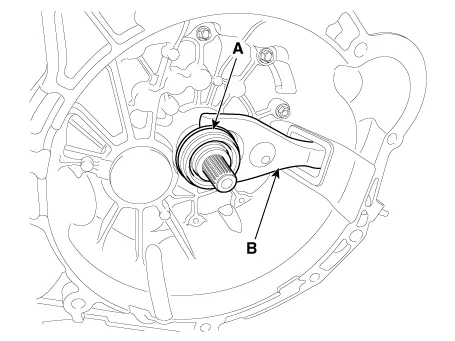
5.Install the clutch release fork (B), clutch release bearing (A).
6.Install the transaxle assembly.(Refer to Manual Transaxle System - "Manual Transaxle")
Other information:
Hyundai Accent (HC) (2017 - 2022) Service Manual: FCA Radar
- Schematic Diagram - Terminal Function NoTerminal function 1- 2C-CAN LOW 3C-CAN HIGH 4GND 5IGN1 6- 7- 8- - Inspection FCA function ON / OFF switch was included to USM (User Setting Menu) and the state of the factory is ON.When the IGN ON, maintain ON condition by default. And does not reflect the driver settings when next IGN ON.Hyundai Accent (HC) (2017 - 2022) Service Manual: Specifications
- Specifications ItemsSpecification HoodTypeFront opening type, rear hinged, stay rod type Front DoorConstructionFront hinged, frame door construction Regulator systemWire drum type Locking systemPin - fork system Rear DoorConstructionFront hinged, frame door construction Regulator systemWire drum type Locking systemPin - fork system Trunk LidTypeTorsior bay type Seat BeltsFront3 point type with Emergency Locking Retractor (E.
Contents
- Clutch Cover And Disc
- Ignition Lock Switch
- Clutch Switch
- Clutch Pedal
- Clutch Tube
- Clutch Master Cylinder
- Concentric Slave Cylinder Assembly
- Clutch Release Cylinder
- Clutch Release Fork and Clutch Release Bearing
Categories
- Manuals Home
- Hyundai Accent Owners Manual
- Hyundai Accent Service Manual
- New on site
- Most important about car

