Hyundai Accent: Air Conditioning System / Evaporator Temperature Sensor
1.Turn the ignition switch OFF.
2.Disconnect the evaporator temperature sensor connector.
3.Measure the resistance between terminal "+" and "-" of the evaporator temperature sensor.
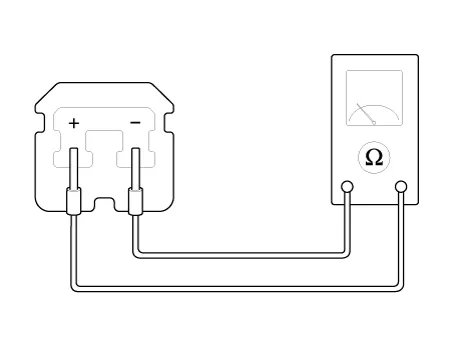
| Evaporator core temperature [°C (°F)] | Resistance [KΩ] | Voltage [V] |
| -10 (14) | 43.35 | 2.96 |
| 0 (32) | 27.62 | 2.4 |
| 10 (50) | 18.07 | 1.88 |
| 20 (68) | 12.11 | 1.44 |
| 30 (86) | 8.30 | 1.08 |
| 40 (104) | 5.81 | 0.81 |

1. Sensor Ground
2. Evaporator sensor (+)
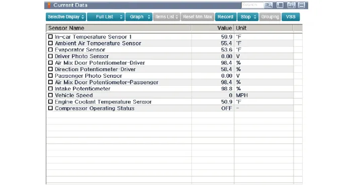
1.The heating, ventilation and air conditioning can be quickly diagnosed failed parts with vehicle diagnostic system (GDS).※ The diagnostic system (GDS) provides the following information.(1) Self diagnosis : Checking the failure code (DTC) and display.(2) Current data : Checking the system input / output data state.(3) Actuation test : Checking the system operation condition.(4) Additional function : Other controlling such as he system option and zero point adjustment.
2.Select the 'Car model' and the system to be checked in order to check the vehicle with the tester.
3.Select the 'Current data' menu to search the current state of the input / output data.The input / output data for the sensors corresponding to the Evaporator Temperature Sensor can be checked.
1.Disconnect the negative (-) battery terminal.
2.Remove the heater and blower unit from the crash pad after loosening the mounting nuts.(Refer to Heater - "Heater Unit")
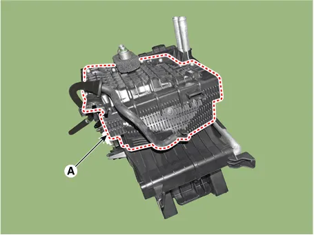
3.Remove the evaporator core cover (A) after loosening the mounting screws.
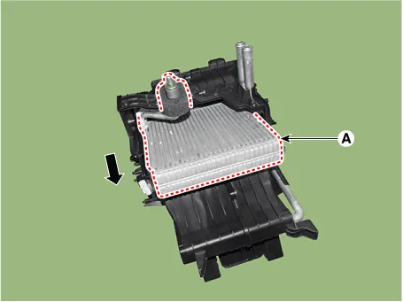
4.Pull out the evaporator core (A) from the heater unit.
5.Remove the evaporator temperature sensor (A) from the evaporator core.
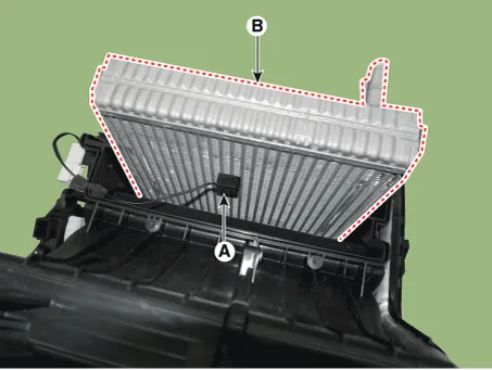
6.To install, reverse the removal procedure.

• If you're installing a new heater core, add refrigerant oil (PAG OIL).
• Replace the O-rings with new ones at each fitting, and apply a thin coat of refrigerant oil before installing them. Be sure to use the right O-rings for R-1234yf to avoid leakage.
• Immediately after using the oil, replace the cap on the container, and seal it to avoid moisture absorption.
• Do not spill the refrigerant oil on the vehicle ; it may damage the paint, if the refrigerant oil contacts the paint, wash it off immediately.
• Apply sealant to the grommets.
• Make sure that there is no air leakage.
• Charge the system and test its performance.
• Do not interchange the inlet and outlet heater hoses and install the hose clamps securely.
Other information:
Hyundai Accent (HC) (2017 - 2022) Service Manual: Troubleshooting
- Troubleshooting SymptomPossible CauseRemedy One lamp does not light(all exterior)Bulb burned outReplace bulb Socket, wiring or ground faultyRepair if necessary Head lamps do not lightBulb burned outReplace bulb Ignition fuse (LOW:10A, HIGH:20A) blownCheck for short and replace fuse Head lamp fuse (15A) blownCheck for short and replace fuse Head lamp relay faultyCheck relay Lighting switch faultyCheck switch Wiring or ground faultyRepair if necessary Tail lamps and license plate lampHyundai Accent (HC) (2017 - 2022) Service Manual: Ignition Lock Switch
- Specifications ItemSpecifications Working voltageDC 12.5V ± 0.3V Operating forceInitial position : 0.25 ± 0.15N(0.025 ± 0.015kg, 0.056 ± 0.034lb) Full position : 0.8 ± 0.2 N(0.08 ± 0.02 kgf, 0.579 ± 0.014 lb-ft) Working temperature-40℃ ~ 80℃ (-40℉ ~ 176℉) - Description – Ignition lock switch is mounted on the clutch pedal.
Categories
- Manuals Home
- Hyundai Accent Owners Manual
- Hyundai Accent Service Manual
- New on site
- Most important about car


