Hyundai Accent: Floor Console / Floor Console Assembly

• Put on gloves to prevent hand injuries.

• When removing with a flat - tip screwdriver or remover, wrap protective tape around the tools to prevent damage to components.
• Use a plastic panel removal tool to remove interior trim pieces without marring the surface.
• Take care not to bend or scratch the trim and panels.
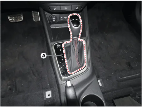
1.Disconnect the gear boots (A).
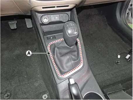
2.Remove the gear knob & boots (A) pull both of it up.
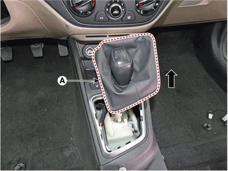
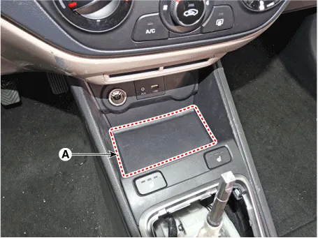
3.Remove the console front tray mat (A).
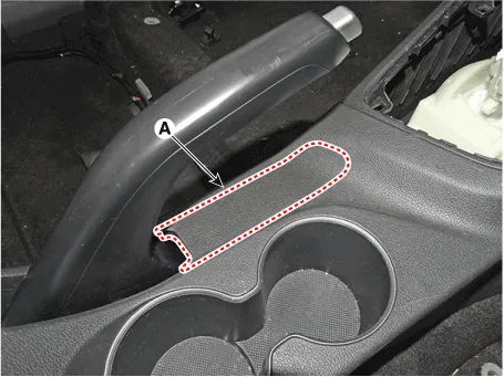
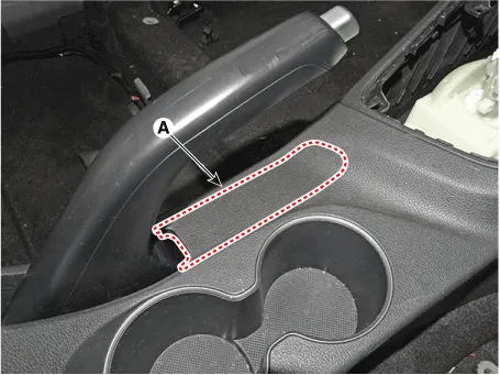
4.Using a screwdriver or remover, remove the parking brake cover (A).
5.Using a screwdriver or remover, remove the console upper cover (A).
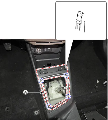
6.Disconnect the connector (A).
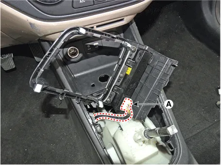
7.Remove the floor console front bezel (A) by pulling it rearward.
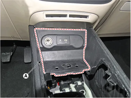
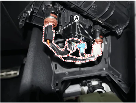
8.Disconnect the connectors (A).
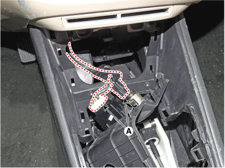
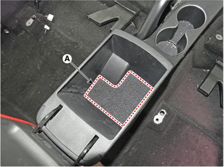
9.Remove the rear console tray mat (A).
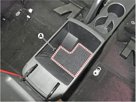
10.Remove the console rear mounting hole cap (A).
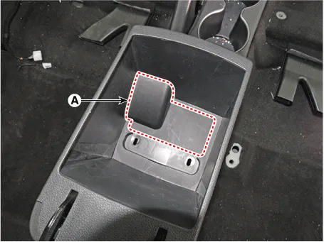
11.After loosening the mounting screws and bolts, remove the console rear complete assembly (A).
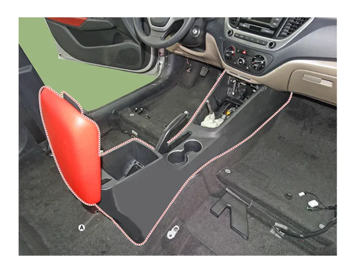
12.To install, reverse the removal procedure.

• Make sure the connector is connected properly.
• Replace any damaged clips (or pin - type retainers).

• Put on gloves to prevent hand injuries.

• When removing with a flat-tip screwdriver or remover, wrap protective tape around the tools to prevent damage to components.
• Use a plastic panel removal tool to remove interior trim pieces without marring the surface.
• Take care not to bend or scratch the trim and panels.
1.To remove the gear knob & gear boots (A) pull both of it up.
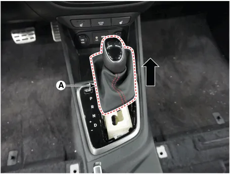
2.Remove the console front tray mat (A).
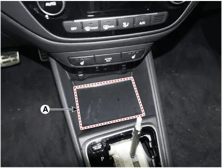
3.Using a screwdriver or remover, remove the console upper cover (A).
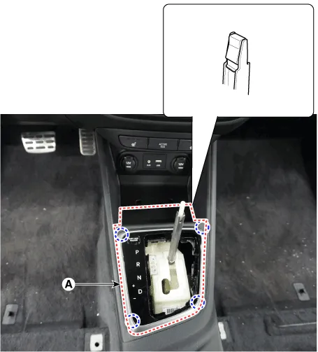
4.Disconnect the connector (A).
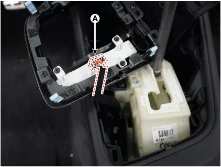
5.Remove the floor console front bezel (A) by pulling it rearward.
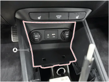
6.Disconnect the connectors (A).
7.Using a screwdriver or remover, remove the parking brake cover (A).
8.Remove the rear console tray mat (A).
9.Remove the consol7e rear mounting hole cap (A).
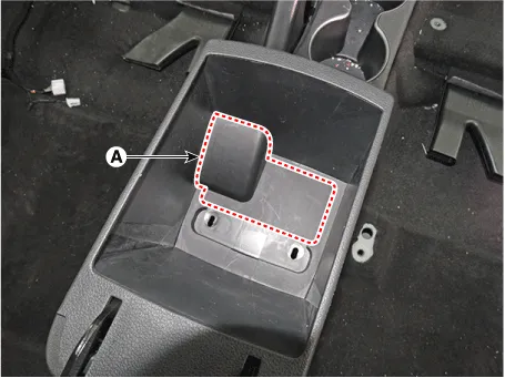
10.After loosening the mounting screws and bolts, remove the console complete assembly (A).
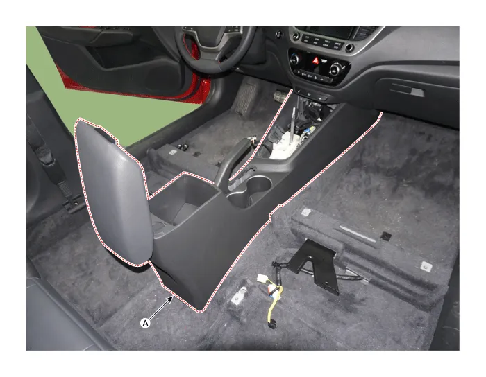
11.To install, reverse removal procedure.

• Make sure the connector is connected properly.
• Replace any damaged clips (or pin - type retainers).
Other information:
Hyundai Accent (HC) (2017 - 2022) Service Manual: Clutch Switch
- Specifications ItemSpecifications Working voltageDC 12.5V ± 0.3V Operating forceInitial position : 0.25 ± 0.15N(0.025 ± 0.015kg, 0.056 ± 0.034lb) Full position : 0.8 ± 0.2 N(0.08 ± 0.02 kgf, 0.579 ± 0.014 lb-ft) Working temperature-40℃ ~ 80℃ (-40℉ ~ 176℉) - Description – Clutch operation is detected through clutch switch signal.Hyundai Accent (HC) (2017 - 2022) Service Manual: Heater Unit
- Component Location 1. Heater unit assembly - Compoents 1. Heater core cover2. Heater core & seal assembly3. Heater case [LH]4. Mode control actuator5. Air guide [LH]6. Heater unit pad7. Deforster door assembly8. Vent door assembly9. Floor door assembly10. Temperature door assembly11. Lower case12. Drain hose13. Heater case [RH]14.
Categories
- Manuals Home
- Hyundai Accent Owners Manual
- Hyundai Accent Service Manual
- New on site
- Most important about car


