Hyundai Accent (HC): Body Electrical System / BCM (Body Control Module)
Contents:
- Specifications
- Components and Components Location
- Schematic Diagrams
- Description and Operation
- Repair procedures
Specifications
| Items | Specifications |
| Rated voltage | DC 12V |
| Operating voltage | DC 9 - 16V |
| Operating temperature | -30°C to 75°C (-4°F to 158°F) |
| Dark current | Keyless type : 3.5 mA Non keyless type : 2.5 mA SMK type : 2.5 mA |
Components and Components Location

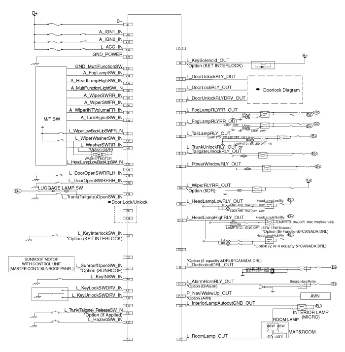
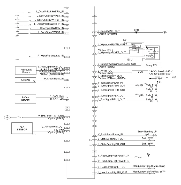
| No | Connector A | Connector B | Connector C | Connector D | Connector |
| 1 | Battery (+) | Front wiper low backup switch input | Static bending light (Left)_output | - | Dedicated DRL output |
| 2 | RPAS power_output | Rear washer switch imput | - | Key Interlock switch input | Tail lamp relay output |
| 3 | Ignition 1 | Rear wiper switch input | B-CAN (High) | - | Power window relay output |
| 4 | Key IN switch | Front wiper switch input | B-CAN (Low) | - | Front fog lamp relay output |
| 5 | - | Front wiper intermittent volume input | Auto light power output | - | Rear fog lamp relay output |
| 6 | Power window lock switch input | Multi function light switch input | Interior lamp autcut ground output | Security ind output | RH Headlamp high output or RH Dedicated DRL otput |
| 7 | Sunroof open switch input | PAS_LIN input | Room lamp output | Key solenoid output | LH Headlamp high output or LH Dedicated DRL otput |
| 8 | Rear right door unlock switch input | - | Turnsignal lamp (Rear Right) output | Head lamp low relay output | Haedlamp high power1 input or Dedicated DRL power1 input |
| 9 | Assist door unlock switch input | - | Turnsignal lamp (Rear Left) output | Rear wiper relay output | Haedlamp high power2 input or Dedicated DRL power2 input |
| 10 | Driver Key unlock switch input | - | Turnsignal lamp (Front Left) output | Navi wake up output | - |
| 11 | Wiper washer switch input | Static bending light input | Tailgate release switch input | Wiper parking state input | Drive door unlock relay output |
| 12 | PAS Power input | Crash signal input | Door open switch (Assist) input | - | Door unlock relay output |
| 13 | - | - | Door open switch (Rear Right) input | AV Tail output | Door lock relay output |
| 14 | ACC | Head lamp high switch input | Door open switch (Driver) input | Start inhibit relay output | - |
| 15 | Ignition 2 | Fog lamp switch input | Door open switch (Rear Left) input | - | Trunk unlock relay output or Tailgate unlock relay output |
| 16 | - | Turn signal lamp switch input | Auto light sensor input | - | - |
| 17 | Hazard switch | Head lamp low backup switch input | Auto light ground output | - | Front wiper high relay output |
| 18 | Power window unlock switch input | - | - | Head lamp high relay output | Front wiper low relay output |
| 19 | Rear left door unlock switch input | Tail gate open switch input | Turnsignal lamp power input | Alarm horn relay output | Safety power window enable output |
| 20 | Driver Key lock switch | - | Front right turnsignal lamp output | - | - |
| 21 | Driver Key lock switch | Multi function switch ground | |||
| 22 | Ground power | Static bending light (Right)_output |
Schematic Diagrams
Description and Operation ➤
Repair procedures
1.Disconnect the negative (-) battery terminal.
2.Remove the crash pad lower panel.(Refer to Body - "Crash Pad Lower Panel")
3.Disconnect the BCM connectors.
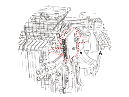
4.Remove the body control module (A) after loosening the mounting bolt and nut.
1.Install the body control module.
2.Connect the body control module.
3.Install the crash pad lower panel.
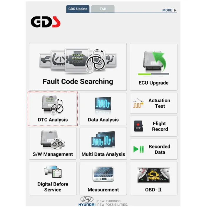
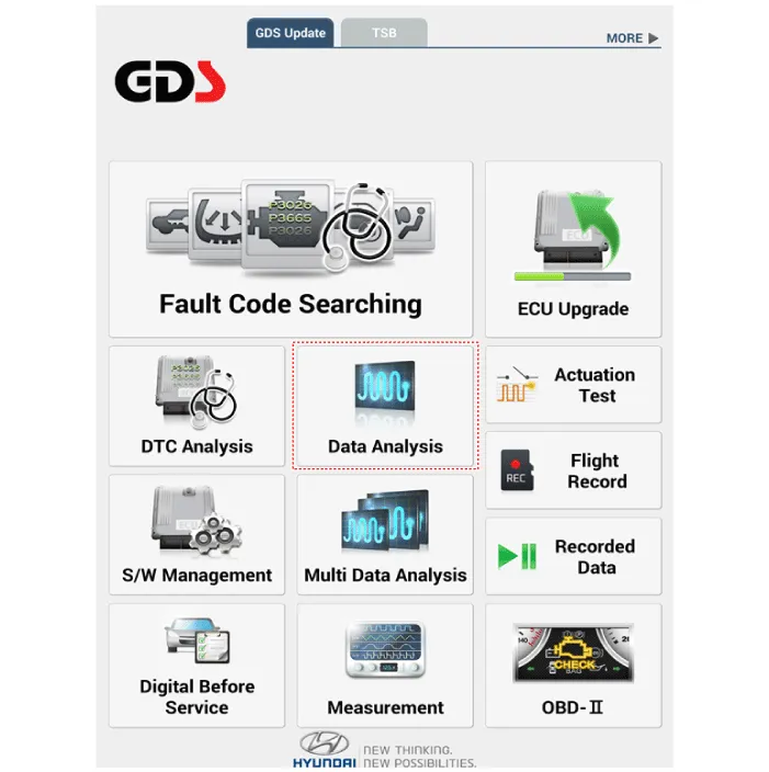
1.In the body electrical system, failure can be quickly diagnosed by using the vehicle diagnostic system (Diagnostic tool).
(1)Fault Code Searching : Checking failure and code number (DTC)
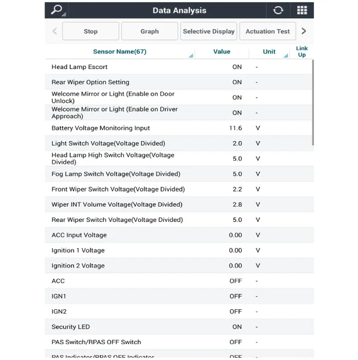
(2)Data Analysis : Checking the system input/output data state
(3)Actuation test : Checking the system operation condition
(4)S/W Management : Controlling other features including system option setting and zero point adjustment
2.If diagnose the vehicle by Diagnostic tool, select "DTC Analysis" and "Vehicle".
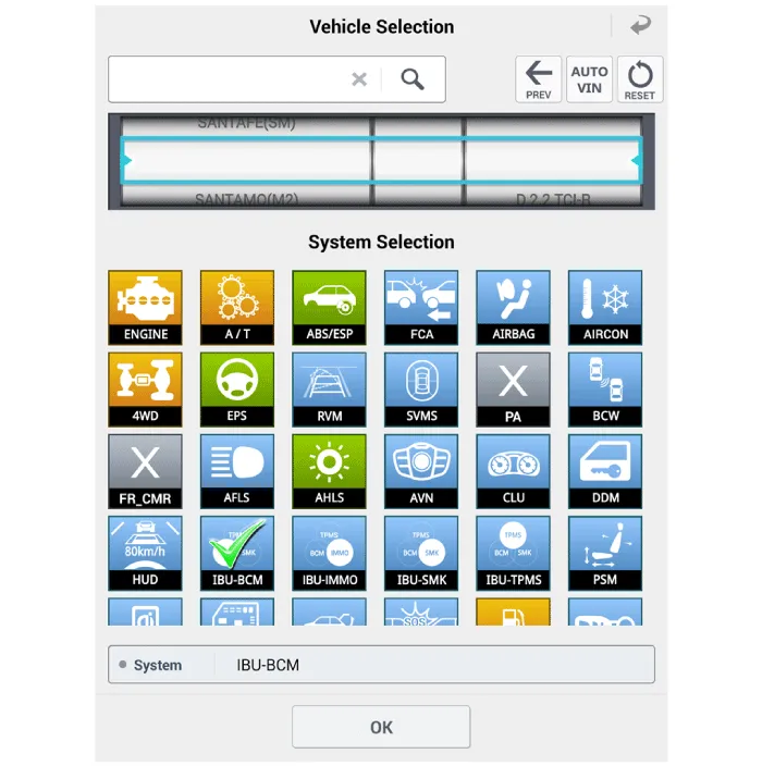
3.If check current status, select the "Data Analysis" and "Car model".
4.Select the 'IBU_BCM' to search the current state of the input/output data.


Other information:
Hyundai Accent (HC) (2017 - 2022) Service Manual: Description and Operation
- Description Burglar Alarm State [B/A State] B/A StateDescription DISARM1) In "DISARM" state, no vehicle start inhibition. So, when door, hood, or Tailgate is opened, there is no alarm sound and flashing. 2) If the battery is disconnected while the state is not "ARM/ARMWAIT/ALARM/REARM", B/A state is set to "DISARM" state. 3)In "DISARM" state, security indicator keeps blinking.Hyundai Accent (HC) (2017 - 2022) Service Manual: Seat Belt Restraint System
In the Hyundai Accent, the seat belt restraint system is designed to hold occupants in the correct position during everyday driving and to help reduce injury risk in a sudden stop or collision. For the best protection, always wear your seat belt correctly and confirm every passenger is properly buckled up before the Hyundai Accent starts moving. WARNING Improperly positioned seat belts may increase the risk of serious injury in an accident.
Contents
- Specifications
- Components and Components Location
- Schematic Diagrams
- Description and Operation
- Repair procedures
Categories
- Manuals Home
- Hyundai Accent Owners Manual
- Hyundai Accent Service Manual
- Questions & Answers
- Video Guides
- Useful Resources
- New on site
- Most important about car
- Privacy Policy

0.0079