Hyundai Accent (HC): ESP(Electronic Stability Program) System / Description and Operation
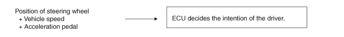
1.STEP 1The ESP analyzes the intention of the driver.
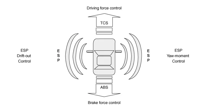
2.STEP 2It analyzes the movement of the ESP vehicle.
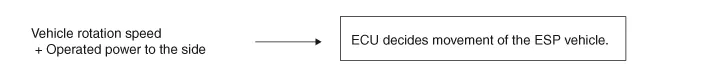
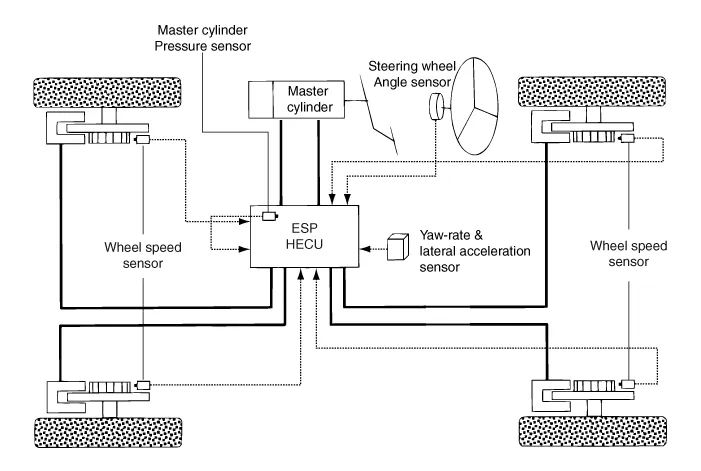
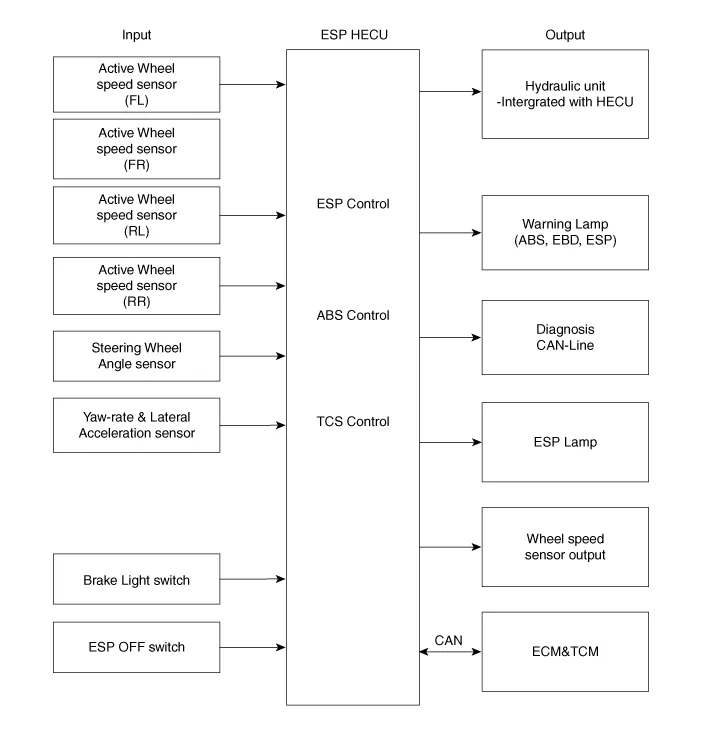
3.STEP 3The HECU calculates the required strategy, then actuates the appropriate valves and sents torque control requests via CAN to maintain vehicle stability.
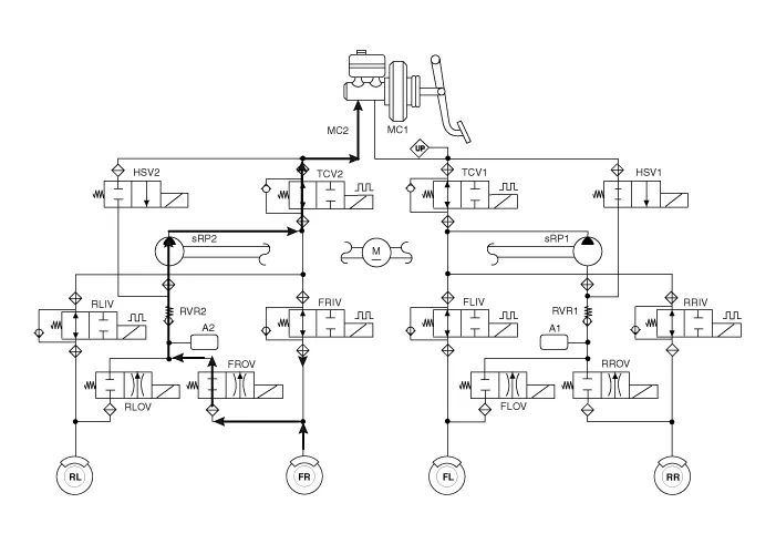
1.ESP Non-operation-Normal braking.
| Inlet valve (IV) | Outlet valve (OV) | Traction Control Valve (TCV) | High pressure switch valve (HSV) | Return pump | |
| Normal braking | Open | Close | Open | Close | OFF |
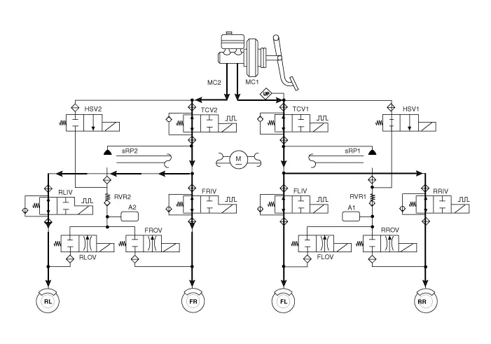

• IV : Inlet Valve
• OV : Outlet Valve
• RL : Rear left wheel
• FR : Front right wheel
• FL : Front left wheel
• RR : Rear right wheel
• RP : Return pump
• TCV : Traction Control Valve
• HSV : High pressure Switch Valve
2.ESP Increase Mode
| Inlet valve (IV) | Outlet valve (OV) | Traction Control Valve (TCV) | High pressure switch valve (HSV) | Return pump | |
| Normal braking | Open | Close | Close (Partial) | Open | ON (Motor speed control) |
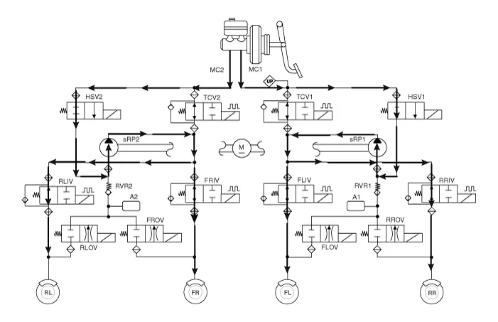

• IV : Inlet Valve
• OV : Outlet Valve
• RL : Rear left wheel
• FR : Front right wheel
• FL : Front left wheel
• RR : Rear right wheel
• RP : Return pump
• TCV : Traction Control Valve
• HSV : High pressure Switch Valve
3.ESP Hold Mode (FR is only controlled.)
| Inlet valve (IV) | Outlet valve (OV) | Traction Control Valve (TCV) | High pressure switch valve (HSV) | Return pump | |
| Normal braking | Close | Close | Close (Partial) | Open | OFF |
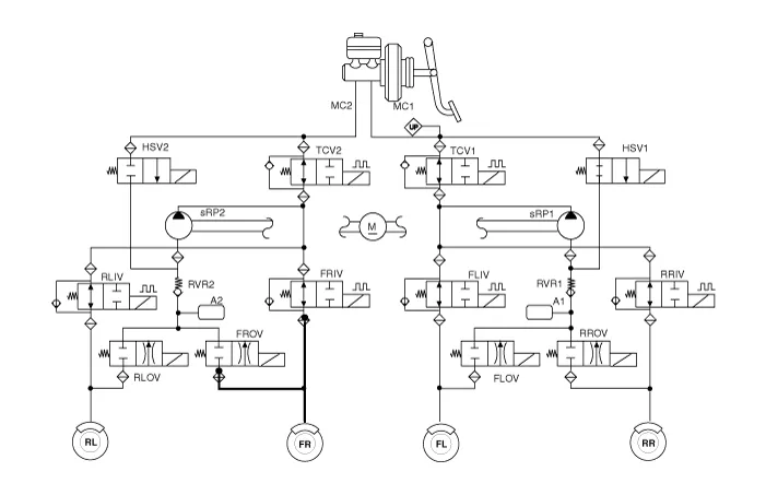

• IV : Inlet Valve
• OV : Outlet Valve
• RL : Rear left wheel
• FR : Front right wheel
• FL : Front left wheel
• RR : Rear right wheel
• RP : Return pump
• TCV : Traction Control Valve
• HSV : High pressure Switch Valve
4.ESP Decrease Mode (FR is only controlled)
| Inlet valve (IV) | Outlet valve (OV) | Traction Control Valve (TCV) | High pressure switch valve (HSV) | Return pump | |
| Normal braking | Close | Open | Close (Partial) | Open | ON (Motor speed low control) |

• IV : Inlet Valve
• OV : Outlet Valve
• RL : Rear left wheel
• FR : Front right wheel
• FL : Front left wheel
• RR : Rear right wheel
• RP : Return pump
• TCV : Traction Control Valve
• HSV : High pressure Switch Valve
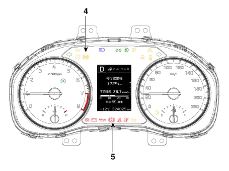
– During the initialization phase after IGN ON. (continuously 3 seconds).
– In the event of inhibition of ESP functions by failure.
– During diagnostic mode.
– When the ECU Connector is separated from ECU.
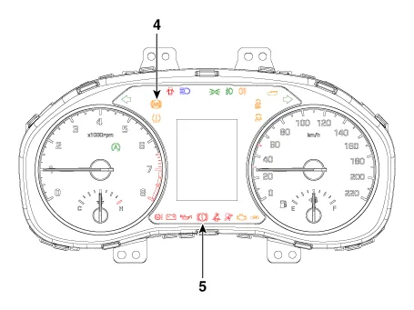
– During the initialization phase after IGN ON. (continuously 3 seconds).
– When the Parking Brake Switch is ON or brake fluid level is low.
– When the EBD function is out of order .
– During diagnostic mode.
– When the ECU Connector is separated from ECU.
– During the initialization phase after IGN ON. (continuously 3 seconds).
– In the event of inhibition of ESP functions by failure.
– During dignostic mode.
– When the ESP control is operating. (Blinking - 2Hz)
– During the initialization phase after IGN ON. (continuously 3 seconds).
– When driver turn off the ESP function by on/off switch.


Other information:
Hyundai Accent (HC) (2017 - 2022) Service Manual: Crankshaft
- Disassembly • Use fender covers to avoid damaging painted surfaces. • To avoid damage, unplug the wiring connectors carefully while holding the connector portion. • Mark all wiring connector and hoses to avoid misconnection. • To release the fuel system pressure before removing the engine assembly, start the engine without fuel pump relay.Hyundai Accent (HC) (2017 - 2022) Service Manual: Changing Tires
WARNING A vehicle can slip or roll off of a jack causing serious injury or death to you or those nearby. Take the following safety precautions: Never place any portion of your body under a vehicle that is supported by a jack. Your Hyundai Accent must be supported only at the correct jacking points and must never be relied on as a “stand.” NEVER attempt to change a tire in the lane of traffic.
Categories
- Manuals Home
- Hyundai Accent Owners Manual
- Hyundai Accent Service Manual
- Questions & Answers
- Video Guides
- Useful Resources
- New on site
- Most important about car
- Privacy Policy

0.009