Hyundai Accent (HC): Brake System (ABS/ESC)
Contents:
- Specifications
- Special Service Tools
- Troubleshooting
- Brake Bleeding Procedures
- Brake System
- Parking Brake System
- ABS(Anti-Lock Brake System)
- ESP(Electronic Stability Program) System
- Forward Collision-Avoidance Assist (FCA) System
Specifications
| Item | Specification | |
| Master cylinder | Type | Single |
| Cylinder I.D. | 20.64 mm | |
| Piston stroke | 36 ± 1 mm (1.41 ± 0.039 in) | |
| Fluid level switch | Provided | |
| Brake booster | Type | 10" Single |
| Boosting ratio | 8.0 : 1 | |
| Front disc brake | Type | Ventilated disc |
| Disc O.D. | Ø 280 mm (11.02 in) | |
| Disc thickness | 22 mm (0.87 in) | |
| Caliper piston | Single | |
| Cylinder I.D. | Ø 54.0 mm (2.13 in) | |
| Rear disc brake | Type | Solid disc |
| Disc O.D. | Ø 262 mm (10.31in) | |
| Disc thickness | 10 mm (0.39 in) | |
| Caliper piston | Single | |
| Cylinder I.D. | Ø 33.96 mm (1.34 in) | |
| Rear drum brake | Type | Leading trailing |
| Drum I.D | Ø 203.2 mm (8 in) | |
| Brake lining thickness | 4.5 mm (0.17 in) | |
| Clearance adjustment | Automatic | |
| Parking brake | Type | BIR (Ball-in-Ramp) |
| Actuation | Lever | |
| Part | Item | Standard value | Remark |
| HECU | System | 4 Channel 4 Sensor (Solenoid) | |
| Type | Motor, valve relay intergrated type | ||
| Operating Voltage | 8 - 16V | ||
| Operating Temperature | -40 - 120°C (-40 - 248°F) | ||
| Motor power | 195W | ||
| Active Wheel speed sensor (ABS) | Supply voltage | DC 4.5 - 20V | |
| Output current low | 5.9 - 8.4 mA | ||
| Output current high | 11.8 - 16.8 mA | ||
| Output range | 1 - 2500 Hz | ||
| Tone wheel | Front : 48 teeth, Rear : 48 teeth | ||
| Air gap | 0.4 - 1.0 mm |
| Part | Item | Standard value | Remark |
| HECU | System | 4 Channel 4 Sensor (Solenoid) | Total control |
| (ABS, EBD, TCS, ESP) | |||
| Type | Motor, valve relay intergrated type | ||
| Operating Voltage | 8 - 16V | ||
| Operating Temperature | -40 - 120°C (-40 - 248°F) | ||
| Motor power | 290W | ||
| Active Wheel speed sensor | Supply voltage | DC 4.5 - 20V | |
| Output current low | 5.9 - 8.4 mA | ||
| Output current high | 11.8 - 16.8 mA | ||
| Output range | 1 - 2,500 Hz | ||
| Tone wheel | Front : 48 teeth, Rear : 48 teeth | ||
| Air gap | 0.4 - 1.0 mm |
| Items | Standard value |
| Brake pedal height | 180.7 mm (7.11 in) |
| Brake pedal Full stroke | 108 mm (4.25 in) |
| Stop lamp switch clearance | 1.0 - 2.0 mm (0.04 - 0.08 in) |
| Brake pedal free play | 2 - 4 mm (0.08 in - 0.16 in) |
| Front brake disc thickness | 22 mm (0.87 in) |
| Front brake disc service limit | 20 mm(0.79 in) |
| Front brake disc pad thickness | 17 mm (0.67 in) |
| Front brake disc pad service limit | 8.0 mm (0.31 in) |
| Rear brake disc thickness | 10 mm (0.39 in) |
| Rear brake disc service limit | 8.4 mm (0.33 in) |
| Rear brake disc pad thickness | 15 mm (0.59 in) |
| Rear brake disc pad service limit | 7.0 mm (0.28 in) |
| Rear drum brake lining thickness | 4.5 mm (0.17 in) |
| Items | N.m | kgf.m | lb-ft |
| Master cylinder to brake booster | 12.7 - 16.7 | 1.3 - 1.7 | 9.4 - 12.3 |
| Brake booster mounting nuts | 16.7 - 25.5 | 1.7 - 2.6 | 12.3 - 18.8 |
| Air bleeding screw | 6.9 - 12.7 | 0.7 - 1.3 | 5.1 - 9.4 |
| Brake tube flare nuts | 12.7 - 16.7 | 1.3 - 1.7 | 9.4 - 12.3 |
| Front caliper guide rod bolts | 21.6 - 31.4 | 2.2 - 3.2 | 15.9 - 23.1 |
| Rear caliper guide rod bolts | 21.6 - 31.4 | 2.2 - 3.2 | 15.9 - 23.1 |
| Front caliper assembly to knuckle | 78.5 - 98.1 | 8.0 - 10.0 | 57.9 - 72.3 |
| Rear caliper assembly to knuckle | 63.7 - 73.5 | 6.5 - 7.5 | 47.0 - 54.2 |
| Brake hose to caliper | 24.5 - 29.4 | 2.5 - 3.0 | 18.1 - 21.7 |
| Brake pedal member bracket bolts | 16.7 - 25.5 | 1.7 - 2.6 | 12.3 - 18.8 |
| Wheel speed sensor mounting bolt | 7.8 - 11.8 | 0.8 - 1.2 | 5.8 - 8.7 |
| HECU bracket mounting and nut | 16.7 - 25.5 | 1.7 - 2.6 | 12.3 - 18.8 |
| Items | Recommended | Quantity |
| Brake fluid | DOT 3 or DOT 4 | As required |
| Brake pedal bushing and bolt | Chassis grease | As required |
| Parking brake shoe and backing plate contacting surface | Heat resistance grease | As required |
Special Service Tools
| Tool(Number and Name) | Illustration | Use |
| 09581-2T100 Piston expander |
| Spreading the front disc brake piston. |
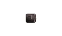
| 09580-0U000 Brake piston adjuster |
| Removal and installtion of the rear disc brake piston. |
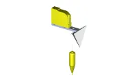
| 09964-C1100 FCA reflector |
| Reflector to align the FCA radar |
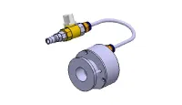
| 09964-C1200 Calibration beam |
| Laser to detect the center of the vehicle. |
| 09964-C1300 Tripod |
| FCA reflector or vertical / horizontal laser support. |
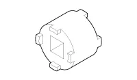
| 09527-1S010 Sensor cap installer |
| Used for installing wheel speed sensor cap (Use with 09231-H1100) |

Troubleshooting
| Symptom | Suspect Area | Reference |
| Lower pedal or spongy pedal | 1. Brake system (Fluid leaks) 2. Brake system (Air in) 3. Piston seals (Worn or damaged) 4. Rear brake shoe clearance (Out of adjustment) 5. Master cylinder (Inoperative) | repair air·bleed replace adjust replace |
| Brake drag | 1. Brake pedal free play (Minimum) 2. Parking brake lever travel (Out of adjustment) 3. Parking brake wire (Sticking) 4. Rear brake shoe clearance (Out of adjustment) 5. Pad or lining (Cracked or distorted) 6. Piston (Stuck) 7. Piston (Frozen) 8. Anchor or Return spring (Inoperative) 9. Booster system (Vacuum leaks) 10. Master cylinder (Inoperative) | adjust adjust repair adjust replace replace replace replace replace replace |
| Brake pull | 1. Piston (Sticking) 2. Pad or lining (Oily) 3. Piston (Frozen) 4. Disc (Scored) 5. Pad or lining (Cracked or distorted) | replace replace replace replace replace |
| Hard pedal but brake inefficient | 1. Brake system (Fluid leaks) 2. Brake system (Air in) 3. Pad or lining (Worn) 4. Pad or lining (Cracked or distorted) 5. Rear brake shoe clearance (Out of adjustment) 6. Pad or lining (Oily) 7. Pad or lining (Glazed) 8. Disc (Scored) 9. Booster system (Vacuum leaks) | repair air·bleed replace replace adjust replace replace replace replace |
| Noise from brake | 1. Pad or lining (Cracked or distorted) 2. Installation bolt (Loosen) 3. Disc (Scored) 4. Sliding pin (Worn) 5. Pad or lining (Dirty) 6. Pad or lining (Glazed) 7. Anchor or Return spring (Faulty) 8. Brake pad shim (Damage) 9. Shoe hold-down spring (Damage) | replace adjust replace replace clean replace replace replace replace |
| Brake fades | 1. Master cylinder (Inoperative) | replace |
| Brake vibration, pulsation | 1. Brake booster (Vacuum leaks) 2. Pedal free play 3. Master cylinder (Inoperative) 4. Caliper (Damage) 5. Master cylinder cap seal 6. Damaged brake lines | replace adjust replace replace replace replace |
| Brake Chatter | Brake chatter is usually caused by loose or worn components, or glazed or burnt linings. Rotors with hard spots can also contribute to brake chatter. Additional causes of chatter are out-of-tolerance rotors, brake lining not securely attached to the shoes, loose wheel bearings and contaminated brake lining. |
Brake Bleeding Procedures

• Do not reuse the drained fluid.
• Always use genuine DOT3/DOT4 brake Fluid.Using a non-genuine DOT3/DOT4 brake fluid can cause corrosion and decrease the life of the system.
• Make sure no dirt or other foreign matter is allowed to contaminate the brake fluid.
• Do not spill brake fluid on the vehicle, it may damage the paint; if brake fluid does contact the paint, wash it off immediately with water.
• The reservoir on the master cylinder must be at the MAX (upper) level mark at the start of bleeding procedure and checked after bleeding each brake caliper. Add fluid as required.
1.Make sure the brake fluid in the reservoir is at the MAX (upper) level line.
2.Have someone slowly pump the brake pedal several times, and then apply pressure.
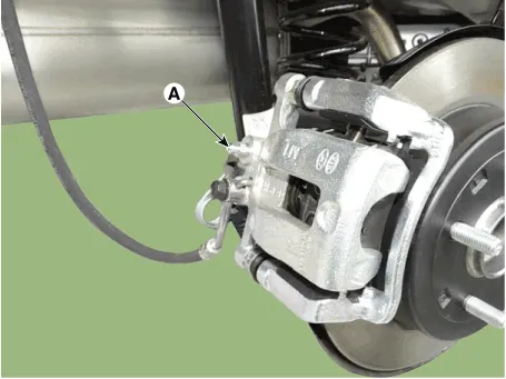
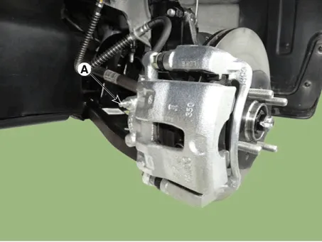
3.Loosen the right-rear brake bleed screw (A) to allow air to escape from the system. Then tighten the bleed screw securely.


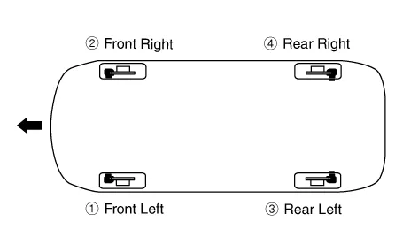
4.Repeat the procedure for wheel in the sequence shown below until air bubbles no longer appear in the fluid.

5.Refill the master cylinder reservoir to MAX (upper) level line.
1.Remove the reservoir cap and fill the brake reservoir with brake fluid.

• If there is any brake fluid on any painted surface, wash it off immediately.
• When pressure bleeding, do not depress the brake pedal.
• Recommended fluid........ DOT3 or DOT4
2.Connect a clear plastic tube to the wheel cylinder bleeder plug and insert the other end of the tube into a half filled clear plastic bottle.
3.Connect the GDS to the data link connector located underneath the dash panel.
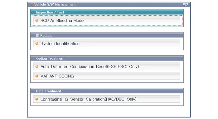
4.Select and operate according to the instructions on the GDS screen

• You must obey the maximum operating time of the ESC motor with the GDS to prevent the motor pump from burning.
1)Select vehicle name.
2) Select ABS/ESC system.
3)Select HCU air bleeding mode.
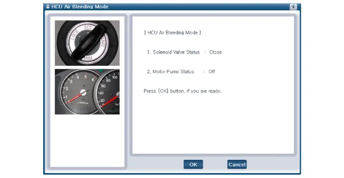
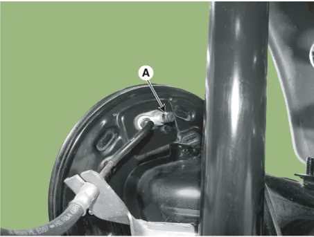
5.Pump the brake pedal several times, and then loosen the bleeder
screw until fluid starts to run out without bubbles. Then close the
bleeder screw (A).

6.Repeat the procedure for wheel in the sequence shown below until air bubbles no longer appear in the fluid.
7.Refill the master cylinder reservoir to MAX (upper) level line.
Brake System ➤
Parking Brake System ➤
ABS(Anti-Lock Brake System) ➤
ESP(Electronic Stability Program) System ➤
Forward Collision-Avoidance Assist (FCA) System ➤


Other information:

Contents
- Specifications
- Special Service Tools
- Troubleshooting
- Brake Bleeding Procedures
- Brake System
- Parking Brake System
- ABS(Anti-Lock Brake System)
- ESP(Electronic Stability Program) System
- Forward Collision-Avoidance Assist (FCA) System
Categories
- Manuals Home
- Hyundai Accent Owners Manual
- Hyundai Accent Service Manual
- Questions & Answers
- Video Guides
- Useful Resources
- New on site
- Most important about car
- Privacy Policy

0.006