Hyundai Accent (HC): Engine Mechanical System / Cylinder Block
Contents:
- Components and Components Location
- Water Jacket Insert
- Drive Plate
- Flywheel
- Rear Oil Seal
- Piston and Connecting Rod
- Crankshaft
- Cylinder Block
Components and Components Location
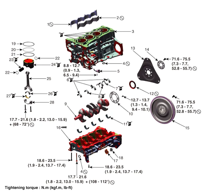
1. RH Water jacket insert
2. LH Water jacket insert
3. Cylinder block
4. O-ring
5. Piston cooling oil jet
6. Crankshaft upper bearing (No.1, 3, 5 journal)
7. Thrust bearing
8. Crankshaft upper bearing (No.2, 4 journal)
9. Crankshaft
10. Crankshaft position sensor wheel
11. Crankshaft lower bearing
12. Rear oil seal
13. Drive plate
14. Drive plate adapter
15. Flywheel
16. Lower crankcase
17. Exus hole cover
18. Rear cap
19. Piston ring (Top ring)
20. Piston ring (Second ring)
21. Piston ring (Oil ring)
22. Snap ring
23. Piston pin
24. Piston
25. Connecting rod
26. Connecting rod upper bearing
27. Connecting rod lower bearing
28. Connecting rod bearing cap
Water Jacket Insert
1.Remove the cylinder head. (Refer to Cylinder Head Assembly - "Cylinder Head")
2.Remove the RH water jacket insert (A) and LH water jacket insert (B).
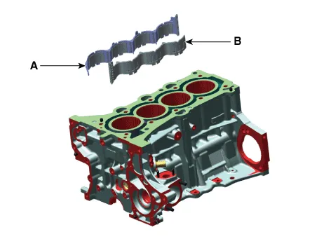

• When removing the water jacket insert, Be careful not to damage the top surfaces of the cylinder block.
3.Install in the reverse order of removal.

• Always use a new water jacket insert.
• Install the upper surface of the water jacket insert below the upper surface of the cylinder block.
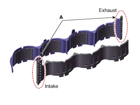
• When installing water jacket insert, check LH, RH classification and installing direction.
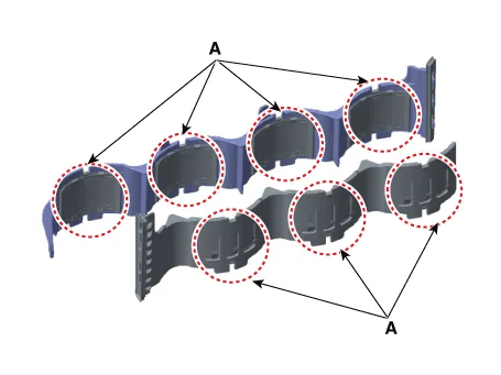
• When installing a new water jacket insert, check the lip seal (A) and the cylinder block mounting surface for foreign matters.
• When installing a new water jacket insert, do not press the sus spring (A).
Drive Plate
1.Remove the intelligent variable transmission (IVT).Remove the automatic transaxle.(Refer to Intelligent Variable Transmission (IVT) System - "Intelligent Variable Transmission (IVT)")
2.Remove the drive plate adapter (A) and drive plate plate (B).
Tightening torque :71.5 - 75.5 N.m (7.3 - 7.7 kgf.m, 52.8 - 55.6 lb-ft)
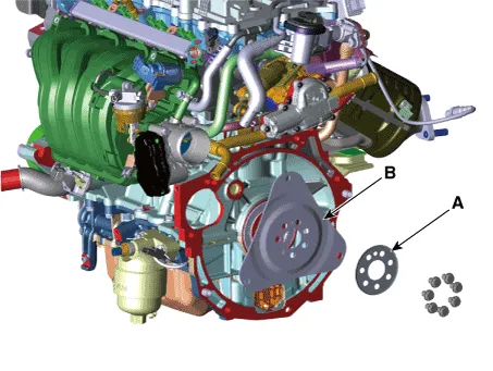

• Always use a new drive plate mounting bolts.
3.Install in the reverse order of removal.
Flywheel
1.Remove the manual transaxle.(Refer to Manual Transaxle System - "Manual Transaxle")
2.Remove the clutch cover.(Refer to Clutch System - "Clutch Cover And Disc")
3.Remove the flywheel (A).
Tightening torque :71.6 - 75.5 N.m (7.3 - 7.7 kgf.m, 52.8 - 55.6 lb-ft)
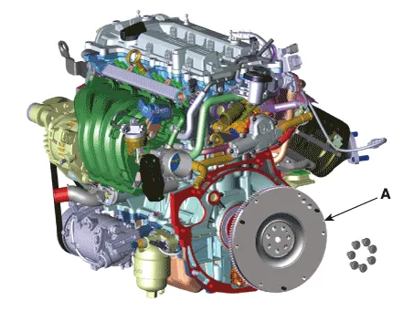

• Always use a new flywheel mounting bolts.
4.Install in the reverse order of removal.
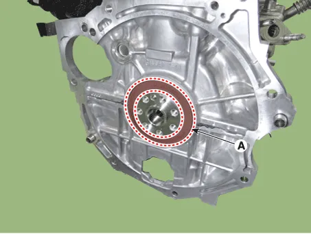
Rear Oil Seal
1.Remove the transaxle assembly from the engine assembly.Intelligent variable transmission (IVT)(Refer to Intelligent Variable Transmission (IVT) System - "Intelligent Variable Transmission (IVT)")Manual transaxle(Refer to Manual Transaxle System - "Manual Transaxle")
2.Intelligent variable transmission (IVT) : Remove the drive plate.(Refer to Cylinder Block - "Drive Plate")Manual transaxle : Remove the flywheel.(Refer to Cylinder Block - "FlyWheel")
3.Remove the rear oil seal (A).
4.Apply engine oil on the edge of new rear oil seal.
5.Using SSTs (09231-H1100, 09231-2B200), install the new rear oil seal. The oil seal installation depth is 0.5 mm (0.0197 in) from the cylinder block face.
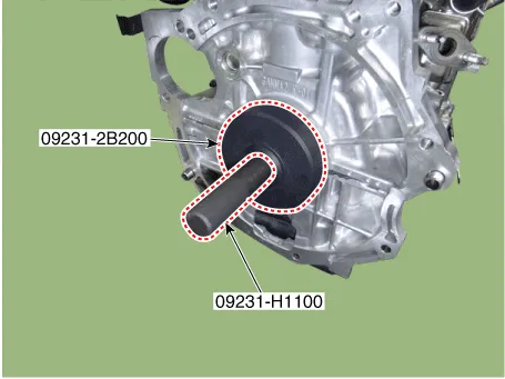

• Always use a new rear oil seal.
6.Install the other parts in the reverse order of removal.
Piston and Connecting Rod ➤
Crankshaft ➤
Cylinder Block

• Use fender covers to avoid damaging painted surfaces.
• To avoid damage, unplug the wiring connectors carefully while holding the connector portion.

• Mark all wiring connector and hoses to avoid misconnection.
• To release the fuel system pressure before removing the engine assembly, start the engine without fuel pump relay. Then, switch "OFF" the ignition when engine stops.
• Turn the crankshaft pulley so that the No. 1 piston is at top dead center.
1.Remove the engine and transaxle assembly. (Refer to Engine and Transaxle Assembly - "Engine and Transaxle Assembly")
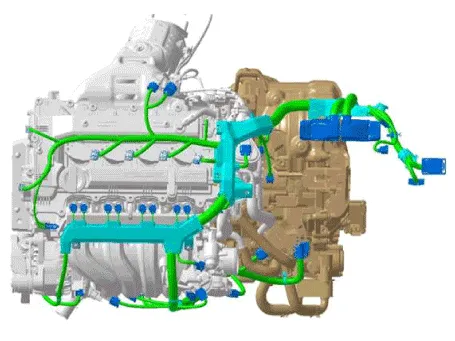
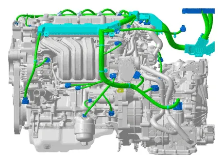
2.Remove the harness clamp from the wiring connector around the engine and transaxle and remove the connector bracket.
3.Remove the transaxle assembly from the engine assembly.Intelligent variable transmission (IVT)(Refer to Intelligent Variable Transmission (IVT) System - "Intelligent Variable Transmission (IVT)")Manual transaxle(Refer to Manual Transaxle System - "Manual Transaxle")
4.Intelligent variable transmission (IVT) : Remove the drive plate.(Refer to Cylinder Block - "Drive Plate")Manual transaxle : Remove the flywheel.(Refer to Cylinder Block - "FlyWheel")
5.Remove the rear oil seal.(Refer to Cylinder Block - "Rear Oil Seal")
6.Install the engine assembly to engine stand for disassembly.
7.Remove the oil pan.(Refer to Lubrication System - "Oil Pan")
8.Remove the timing chain.(Refer to Timing System - "Timing Chain")
9.Remove the intake manifold.(Refer to Intake and Exhaust System - "Intake Manifold")
10.Remove the exhaust manifold.(Refer to Intake and Exhaust System - "Exhaust Manifold")
11.Remove the electric EGR control valve.(Refer to Engine Control / Fuel System - "Electric EGR Control Valve")
12.Remove the EGR cooler.(Refer to Intake and Exhaust System - "EGR Cooler")
13.Remove the oil filter body.(Refer to Lubrication System - "Oil Filter Body")
14.Remove the oil pump.(Refer to Lubrication System - "Oil Pump")
15.Remove the cylinder head.(Refer to Cylinder Head Assembly - "Cylinder Head")
16.Remove the air conditioning compressor.(Refer to Heating, Ventilation and Air Conditioning - "Compressor")
17.Remove the piston and connecting rod assembly. (Refer to Cylinder Block - "Piston and Connecting Rod")
18.Remove the crankshaft.(Refer to Cylinder Block - "Crankshaft")
19.Remove the water jacket insert.(Refer to Cylinder Block - "Water Jacket Insert")
20.Remove the knock sensor.(Refer to Engine Control / Fuel System - "Knock Sensor (KS)")
21.Remove the crankshaft position sensor (CKPS).(Refer to Engine Control / Fuel System - "Crankshaft Position Sensor (CKPS)")
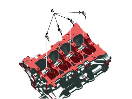
22.Remove the piston cooling oil jets (A).

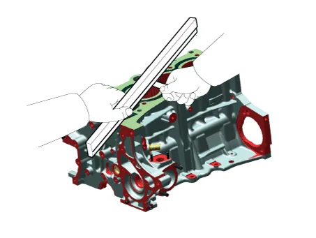
1.Using a gasket scraper, remove all the gasket material from the top surface of the cylinder block.
2.Using a soft brush and solvent, thoroughly clean the cylinder block.
3.Inspect the top surface of cylinder block for flatness.Using a precision straight edge and feeler gauge, measure the surface contacting the cylinder head gasket for warpage.
Flatness of cylinder block gasket surface :Less than 0.05 mm (0.0020 in.) for total areaLess than 0.02 mm (0.0008 in.) for a section of 100 mm x 100 mm (3.9370 in x 3.9370 in.)
4.Visually check for scratches on the inside surface of the cylinder bore and replace the cylinder block if any noticeable scratch is detected. If deep scratchs are present, replace the cylinder block.
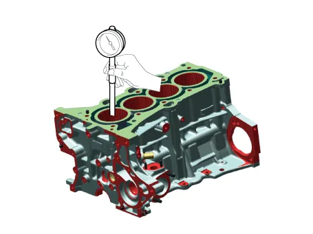
5.Using the cylinder bore gauge, measure the cylinder bore’s inner diameter to the axial and axial perpendicular directions.
Cylinder bore diameter : 75.60 - 75.63 mm (2.9764 - 2.9776 in.)

• Thoroughly clean all parts to assembled.
• Before installing the parts, apply fresh engine oil to all sliding and rotating surfaces.
• Always use new gaskets, O-ring and oil seals.
1.Install the piston cooling oil jets (A).
Tightening torque : 8.8 - 12.7 N.m (0.9 - 1.3 kgf.m, 6.5 - 9.4 lb-ft)
2.Install the crankshaft.(Refer to Cylinder Block - "Crankshaft")
3.Check the crankshaft end play.(Refer to Cylinder Block - "Crankshaft")
4.Disconnect the lower crankcase and check crankshaft bearing oil clearance.(Refer to Cylinder Block - "Crankshaft")
5.Install the piston and connecting rod assembly.(Refer to Cylinder Block - "Piston and Connecting Rod")
6.Check the connecting rod bearing cap oil clearance.(Refer to Cylinder Block - "Piston and Connecting Rod")
7.Check the connecting rod end play. (Refer to Cylinder Block - "Piston and Connecting Rod")
8.Assemble the other parts in the reverse order of disassembly.

• In case the cylinder block is replaced with a new one, select the proper crankshaft main bearing and the piston according to the crankshaft journal bore mark and the cylinder bore mark on the cylinder block.
• Crankshaft main bearing selection(Refer to Cylinder Block - "Crankshaft")
• Piston selection(Refer to Cylinder Block - "Piston and Connecting Rod")


Other information:
Hyundai Accent (HC) (2017 - 2022) Service Manual: Description and Operation
- Function NoItemDescription 1Washer Linked Wiper – If the washer switch is pressed ON for 0.06 second with the vehicle mode in IGN2, the wiper relay is turned ON after washer switch ON, and then the wiper relay is turned OFF after wiper parking signal ON. 2MIST Linked Wiper – If the wiper mist switch is pressed ON for 0.6 second with the vehicle mode in IGN2, the wiper relay is turned ON, and then OFF after wiper parking signal ON.Hyundai Accent (HC) (2017 - 2022) Service Manual: Remote Key
The Hyundai Accent is equipped with a convenient remote key that lets you lock or unlock a door (and the trunk) quickly, and on some Hyundai Accent configurations it can also be used as part of the normal engine-start procedure. Keep the remote key with you so you can access your Hyundai Accent safely and efficiently wherever you park. 1. Door Lock 2.
Contents
- Components and Components Location
- Water Jacket Insert
- Drive Plate
- Flywheel
- Rear Oil Seal
- Piston and Connecting Rod
- Crankshaft
- Cylinder Block
Categories
- Manuals Home
- Hyundai Accent Owners Manual
- Hyundai Accent Service Manual
- Questions & Answers
- Video Guides
- Useful Resources
- New on site
- Most important about car
- Privacy Policy

0.0076