Hyundai Accent (HC): Engine Mechanical System
Contents:
- Specifications
- Repair procedures
- Troubleshooting
- Special Service Tools
- Engine And Transaxle Assembly
- Timing System
- Cylinder Head Assembly
- Cylinder Block
- Cooling System
- Lubrication System
- Intake And Exhaust System
Specifications ➤
Repair procedures

• If the there is lack of power, excessive oil consumption or poor fuel economy, measure the compression pressure.
1.Start the engine and turn the coolant temperature to 80 - 95 °C and stop.
2.Remove the engine cover.(Refer to Engine and Transaxle Assembly - "Engine Cover")
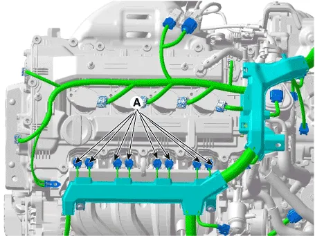
3.Disconnect the injector connectors (A).
4.Remove the ignition coils.(Refer to Engine Electical System - "Ignition Coil")
5.Remove spark plugs.(Refer to Engine Electrical System - "Spark Plug")
6.Check the cylinder compression pressure.
(1)Insert a compression gauge into the spark plug hole.
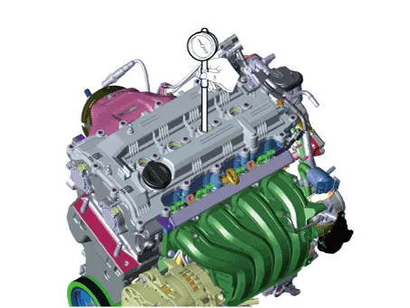
(2)Fully open the throttle valve.
(3)While cranking the engine, measure the compression pressure.

• Always use a fully charged battery to obtain engine speed of 200 rpm or more.
(4)Repeat steps (1) through (3) for each cylinder.

• If you need to check the compression pressure for more than three times, restart the engine to restore the lubrication condition to be normal and then check the compression pressure again.
Compression pressureStandard : 1225.83kPa (12.5kg/cm, 177.79psi) (200-250 rpm)Minimum : 1078.73kPa (11.0kg/cm, 156.46psi)Difference between each cylinder : 98 kPa (1.0 kg/cm, 14 psi) or less
(5)If the cylinder compression in 1 or more cylinders is low, pour a small amount of engine oil into the cylinder through the spark plug hole and repeat steps (1) through (3) for cylinders with low compression.
• If adding oil helps the compression, it is likely that the piston rings and/or cylinder bore are worn or damaged.
• If pressure stays low, a valve may be sticking or seating is improper, or there may be leakage past the gasket.
7.Install the spark plugs.(Refer to Engine Electrical System - "Spark Plug")
8.Install the ignition coil.(Refer to Engine Electical System - "Ignition Coil")
9.Connect the injector connectors (A).

10.Some DTCs may exist after the inspection test and may need to be manually cleared with GDS.
11.Install the engine cover.(Refer to Engine and Transaxle Assembly - "Engine Cover")
Troubleshooting
| Symptom | Suspect area | Remedy | ||||||||
| Engine misfire with abnormal internal lower engine noises. | Loose or improperly installed drive plate. | Repair or replace the drive plate as required. | ||||||||
| Worn piston rings. (Oil consumption may or may not cause the engine to misfire.) | Inspect the cylinder for a loss of compression . Repair or replace as required. | |||||||||
| Worn crankshaft thrust bearings. | Replace the crankshaft and bearings as required. | |||||||||
| Engine misfire with abnormal valve train noise. | Stuck valves. (Carbon buildup on the valve stem can cause the valve not to close properly.) | Repair or replace as required. | ||||||||
| Excessive worn or mis-aligned timing chain. | Replace the timing chain and sprocket as required. | |||||||||
| Worn camshaft lobes. | Replace the camshaft and HLA. | |||||||||
| Engine misfire with coolant consumption. |
|
| ||||||||
| Engine misfire with excessive oil consumption. | Worn valves, valve guides and/or valve stem oil seals. | Repair or replace as required. | ||||||||
| Worn piston rings. (Oil consumption may or may not cause the engine to misfire) | Inspection the cylinder for a loss of compression. Repair or replace as required. | |||||||||
| Engine noise on start-up, but only lasting a few seconds. | Incorrect oil viscosity. | Drain the oil. Install the correct viscosity oil. | ||||||||
| Worn crankshaft thrust bearing. | Inspect the thrust bearing and crankshaft. Repair or replace as required. | |||||||||
| Upper engine noise, regardless of engine speed. | Low oil pressure. | Repair or replace as required. | ||||||||
| Broken valve spring. | Replace the valve spring. | |||||||||
| Worn or dirty valve lifters. | Replace the valve lifters. | |||||||||
| Stretched or broken timing chain and/or damaged sprocket teeth. | Replace the timing chain and sprockets. | |||||||||
| Worn timing chain tensioner, if applicable. | Replace the timing chain tensioner as required. | |||||||||
| Worn camshaft lobes. | Inspect the camshaft lobes. Replace the camshaft and valve lifters as required. | |||||||||
| Worn valve guides or valve stems. | Inspect the valves and valve guides, then repair as required. | |||||||||
| Stuck valves. (Carbon on the valve stem or valve seat may cause the valve to stay open.) | Inspect the valves and valve guides, then repair as required. | |||||||||
| Lower engine noise, regardless of engine speed. | Low oil pressure. | Repair or replace damaged components as required. | ||||||||
| Loose or damaged drive plate. | Repair or replace the drive plate. | |||||||||
| Damaged oil pan, contacting the oil pump screen. | Inspect the oil pan. Inspect the oil pump screen. Repair or replace as required. | |||||||||
| Oil pump screen loose, damaged or restricted. | Inspect the oil pump screen. Repair or replace as required. | |||||||||
| Excessive piston-to-cylinder bore clearance. | Inspect the piston and cylinder bore. Repair as required. | |||||||||
| Excessive piston pin-to-bore clearance. | Inspect the piston, piston pin and the connecting rod. Repair or replace as required. | |||||||||
| Excessive connecting rod bearing clearance. | Inspect the following components and repair as required.
| |||||||||
| Excessive crankshaft bearing clearance. | Inspect the following components and repair as required.
| |||||||||
| Incorrect piston, piston pin and connecting rod installation. | Verify the piston pins and connecting rods are installed correctly. Repair as required. | |||||||||
| Engine noise under load. | Low oil pressure. | Repair or replace as required. | ||||||||
| Excessive connecting rod bearing clearance. | Inspect the following components and repair as required.
| |||||||||
| Excessive crankshaft bearing clearance. | Inspect the following components and repair as required.
| |||||||||
| Engine will not crank. (crankshaft will not rotate) | Hydraulically locked cylinder.
| Remove spark plugs and check for fluid. Inspect for broken head gasket. Inspect for cracked engine block or cylinder head. Inspect for a sticking fuel injector and/or leaking fuel regulator. | ||||||||
| Broken timing chain and/or timing chain gears. | Inspect timing chain and gears. Repair as required. | |||||||||
Foreign material in cylinder.
| Inspect cylinder for damaged components and/or foreign materials. Repair or replace as required. | |||||||||
| Seized crankshaft or connecting rod bearings. | Inspect crankshaft and connecting rod bearing. Repair or replace as required. | |||||||||
| Bent or broken connecting rod. | Inspect connecting rods. Repair or replace as required. | |||||||||
| Broken crankshaft. | Inspect crankshaft. Repair or replace as required. |
Special Service Tools
| Tool (Number and name) | Illustration | Use |
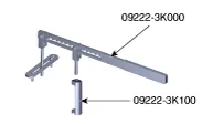
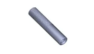
| Valve spring compressor (09222-3K000) Valve spring compressor adapter (09222-3K100) |
| Removal and installation of the intake / exhaust valve spring and retainer lock |
| Valve stem seal installer (09222-2B100) |
| Installation of the valve stem seal |
| Oil pan remover (09215-3C000) |
| Removal of oil pan |
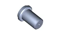
| Crankshaft front oil seal installer (0K231-2C200) |
| Installation of the crankshaft front oil seal |
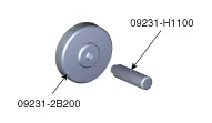
| Crankshaft rear oil seal installer (09231-2B200) Handle (09231-H1100) |
| Installation of the crankshaft rear oil seal |
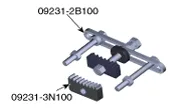
| Ring gear stopper (09231-3N100) |
| Removal and installation of crankshaft damper pulley bolt |

Engine And Transaxle Assembly ➤
Timing System ➤
Cylinder Head Assembly ➤
Cylinder Block ➤
Cooling System ➤
Lubrication System ➤
Intake And Exhaust System ➤


Other information:
Hyundai Accent (HC) (2017 - 2022) Service Manual: Phone
Information - Using Bluetooth® Wireless Technology(BT) Cellular Phone Bluetooth® Wireless Technology is a near-field wireless networking technology that uses the 2.4 GHz frequency to connect various devices within a certain distance wirelessly. In the Hyundai Accent, Bluetooth® Wireless Technology supports handsfree calling and (when compatible) media streaming.Hyundai Accent (HC) (2017 - 2022) Service Manual: Troubleshooting
Standard Flow of Diagnostic Troubleshooting Notes With Regard To Diagnosis The phenomena listed in the following table are not abnormal.ConditionExplanation System check soundWhen starting the engine, a thudding sound can sometimes be heard coming from inside the engine compartment. This is because the system operation check is being performed.
Contents
- Specifications
- Repair procedures
- Troubleshooting
- Special Service Tools
- Engine And Transaxle Assembly
- Timing System
- Cylinder Head Assembly
- Cylinder Block
- Cooling System
- Lubrication System
- Intake And Exhaust System
Categories
- Manuals Home
- Hyundai Accent Owners Manual
- Hyundai Accent Service Manual
- Questions & Answers
- Video Guides
- Useful Resources
- New on site
- Most important about car
- Privacy Policy

0.0089