Hyundai Accent (HC): Engine Mechanical System / Lubrication System
Contents:
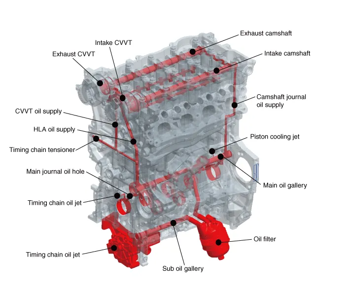
Flow Diagram
Engine Oil

• Prolonged and repeated contact with mineral oil will result in the removal of natural fats from the skin, leading to dryness, irritation and dermatitis. In addition, used engine oil contains potentially harmful contaminants which may cause skin cancer.
• Exercise caution in order to minimize the length and frequency of contact of your skin to used oil. Wear protective clothing and gloves. Wash your skin thoroughly with soap and water, or use water-less hand cleaner, to remove any used engine oil. Do not use gasoline, thinners, or solvents.
• In order to preserve the environment, used oil and used oil filter must be disposed of only at designated disposal sites.
1.Drain the engine oil.
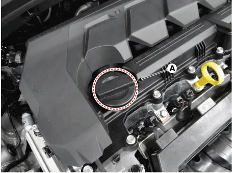
(1)Remove the oil filler cap (A).

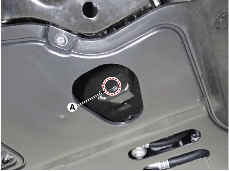
(2)Remove the oil drain plug (A), and drain the oil into a container.

2.Replace the oil filter.
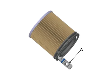
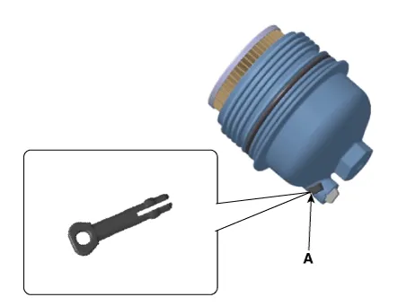
(1)Remove the safety pin (A).
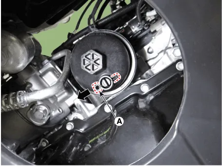
(2)Remove the pre-drain plug (A) by rotating it by 90° and then drain the engine oil in the oil filter.
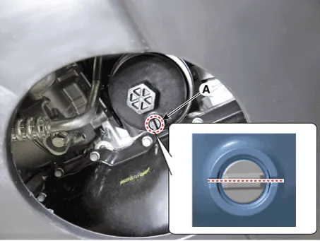
(3)Using the socket wrench, remove the oil filter cap (A).

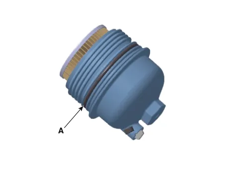
(4)Install the new o-ring (A) on the oil filter cap.
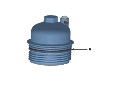

• Always use a new O-ring.
(5)Install the new oil filter (A).
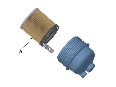

• When install the oil filter, apply engine oil to the drain plug O-ring (A).
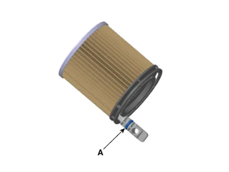
• Must use the drain plug (A) that is installed in a new oil filter.
(6)Rotate the free drain plug (A) by 90° so that the drain pin is in the locked position.
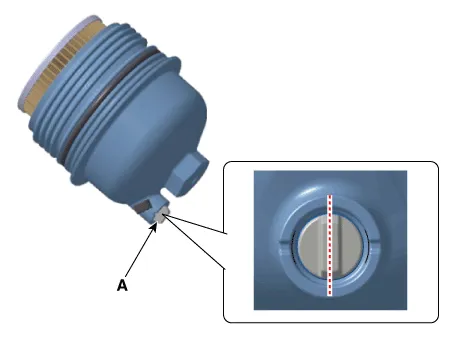
(7)Install the new safety pin (A).

• Always use a safety pin.
(8)Lightly tighten the O-ring of the oil filter cap until it contacts with the installed surface, then tighten the oil filter cap (A) to the specified torque using a socket wrench..
Tightening torque :34.3 N.m (3.5 kgf.m, 25.3 lb-ft)

• When install the oil filter cap, Check if the new o-ring (A) is installed correctly the cap.
• When install the oil filter cap, apply engine oil to the new O-ring (A).
3.Refill with engine oil.
(1)Install the oil drain plug (A) with a new gasket.
Tightening torque :34.3 - 44.1 N.m (3.5 - 4.5 kgf.m, 25.3 - 32.5 lb-ft)
(2)Fill with fresh engine oil.
CapacityTotal : 4.0 L (4.23 US qt, 3.52 lmp.qt., 1.06 US gal.)Oil pan : 3.6 L (3.8 U.S qt., 3.17 lmp.qt., 0.95 U.S gal.)Drain and refill including oil filter : 3.8 L (4.02 U.S qt., 3.34 lmp.qt., 1.00 U.S gal.)
(3)Intall the oil filler cap (A).
4.Start engine and check for oil leaks.
5.Recheck the engine oil level.
1.Check the engine oil quality.Check the oil deterioration, entry of water, discoloring of thinning.If the quality is visibly poor, replace the oil.
2.Check the engine oil level.After warning up the engine and then 5 minutes after the engine stop, oil level should be between the "L" and "F" marks in the dipstick.If low, check for leakage and add oil up to the "F" mark.

• Do not fill with engine oil above the "F" mark.
• Check the oil level gauge, based on a condition in which the engine oil temperature is a room temperature (20°C – 25°C).
• Make sure the tire pressure falls within the normal range.
• When measuring engine oil, make sure the road surface is even.
• After draining engine oil, make sure you check the total amount of drained oil before injection.
Oil Filter Body
1.Disconnect the battery negative terminal.
2.Remove the engine room under cover.(Refer to Engine and Transaxle Assembly - "Engine Room Under Cover")
3.Drain the engine oil.(Refer to Lubrication System - "Engine Oil")
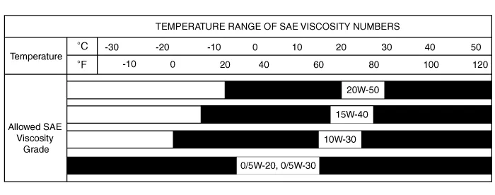
4.Disconnect the oil pressure switch connector (A).
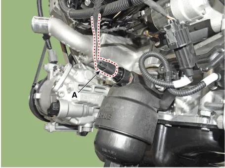
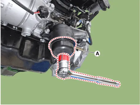
5.Remove the oil filter body (A).
Tightening torque :18.6 - 23.5 N.m (1.9 - 2.4 kgf.m, 13.7 - 17.4 lb-ft)
6.Install in the reverse order of removal.
7.Refill engine oil.(Refer to Lubrication System - "Engine Oil")
Oil Pan
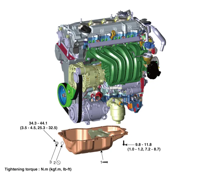
1. Oil pan
2. Oil drain plug gasket
3. Oil drain plug
1.Remove the engine room under cover.(Refer to Engine and Transaxle Assembly System - "Engine Room Under Cover")
2.Drain the engine oil. (Refer to Lubrication System - "Engine Oil")
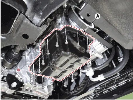
3.Using the SST (09215-3C000) and remove the oil pan (A).
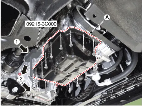

• Insert the SST between the oil pan and the ladder frame by tapping it with a plastic hammer in the direction of ①arrow.
• After tapping the SST with a plastic hammer along the direction of ② arrow around more than 2/3 edge of the oil pan, remove it from the cylinder block.

• Do not turn over the SST abruptly without tapping. It be result in damage of the SST.
1.Install the oil pan.
(1)Before assembling the oil pan, the surface where the sealant is applied to should be free from the hardened sealant, foreign matters, oil, dust, moisture and etc.
(2)After applying liquid sealant on the oil pan, assemble it within 5 minutes.
Width : 2.5 - 3.5 mm (0.0984 - 0.1378 in.)Specification : LOCTITE 5900H / THREE BOND 1217H or above.
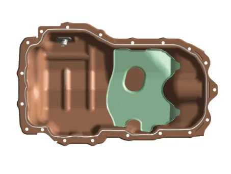

• When applying sealant gasket, sealant must not be protruded into the inside of oil pan.
• To prevent leakage of oil, apply sealant gasket to the inner threads of the bolt holes.
• If the sealant is applied to the bottom surface of the lower crankcase, it should be the same position as the oil pan.
(3)Install the oil pan (A) with the bolts.Uniformly tighten the bolts in several passes.
Tightening torque :9.8 - 11.8 N.m (1.0 - 1.2 kgf.m, 7.2 - 8.7 lb-ft)

• After assembly, wait at least 30 minutes before filling the engine with oil.
2.Refill engine oil.(Refer to Lubrication System - "Engine Oil")
Oil Pump
1.Remove the engine room under cover.(Refer to Engine and Transaxle Assembly - "Engine Room Under Cover")
2.Drain the engine oil.(Refer to Lubrication System - "Engine Oil")
3.Remove the oil pan.(Refer to Lubrication System - "Oil Pan")
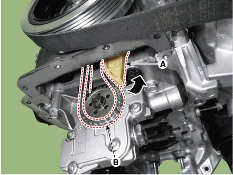
4.Turn the oil pump chain tensioner (A) in the direction of the arrow and remove the oil pump chain (B) from the oil pump.
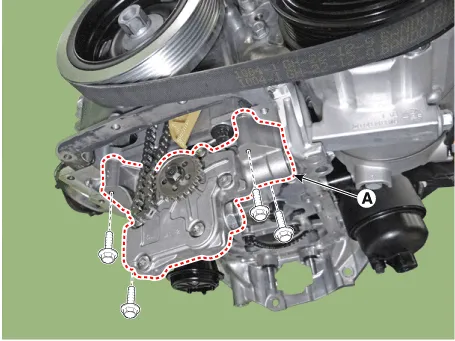
5.Remove the oil pump (A).
Tightening torque :18.6 - 23.5 N.m (1.9 - 2.4 kgf.m, 13.7 - 17.4 lb-ft)
6.Install in the reverse order of removal.
7.Refill engine oil.(Refer to Lubrication System - "Engine Oil")
8.Start engine and check for oil leaks.
1.Disconnect the battery negative terminal.
2.Remove the timing chain.(Refer to Timing System - "Timing Chain")
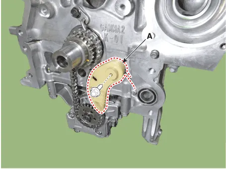
3.Remove the oil pump chain tensioner (A).
Tightening torque :9.8 - 11.8 N.m (1.0 - 1.2 kgf.m, 7.2 - 8.7 lb-ft)
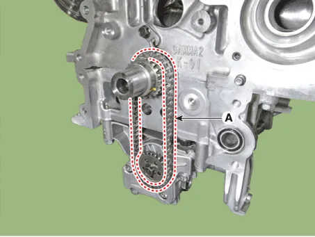
4.Remove the oil pump chain (A).
5.Install in the reverse order of removal.
6.Refill engine oil.(Refer to Lubrication System - "Engine Oil")
Oil Pressure Switch
1.Disconnect the battery negative terminal.
2.Remove the engine room under cover.(Refer to Engine and Transaxle Assembly System - "Engine Room Under Cover")
3.Drain the engine oil. (Refer to Lubrication System - "Engine Oil")
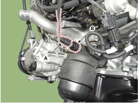
4.Disconnect the oil pressure switch connector (A).
5.Remove the oil pressure switch (B).
Tightening torque :14.7 - 21.6 N.m (1.5 - 2.2 kgf.m, 10.8 - 15.9 lb-ft)
6.Installation is in the reverse order of removal.

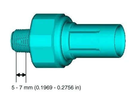
• When installing the oil pressure switch, apply seal lock to the thread.
Seal lock : THREEBOND 2403Thickness : 0.2 - 0.4 mm (0.008 - 0.016 in)
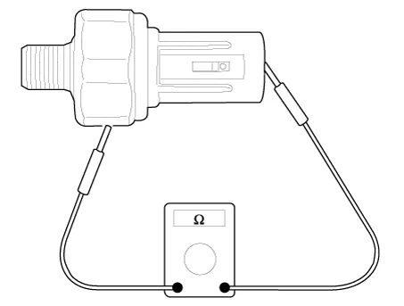
1.Check the continuity between the terminal and the body with an ohmmeter. If there is no continuity, replace the oil pressure switch.
2.Check the continuity between the terminal and the body when the fine wire is pushed. If there is continuity even when the fine wire is pushed, replace the switch.
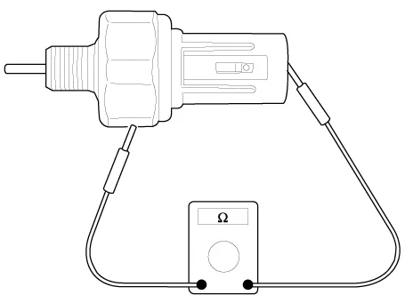
3.If there is no continuity when a 49.0kpa (0.5kg/cm², 7.1psi) vacuum is applied through the oil hole, the switch is operating properly.Check for air leakage. If air leaks, the diaphragm is broken. Replace it.


Other information:
Hyundai Accent (HC) (2017 - 2022) Service Manual: Seat Belt Restraint System
In the Hyundai Accent, the seat belt restraint system is designed to hold occupants in the correct position during everyday driving and to help reduce injury risk in a sudden stop or collision. For the best protection, always wear your seat belt correctly and confirm every passenger is properly buckled up before the Hyundai Accent starts moving. WARNING Improperly positioned seat belts may increase the risk of serious injury in an accident.Front seat 1. Forward and backward — adjust distance to pedals and steering wheel for safe control 2. Seatback angle — set a comfortable upright angle that supports your back 3. Seat height (Driver's seat) — adjust eye level for clear visibility over the hood 4. Headrest — align with the head for whiplash protection in a collision 5. Seat warmer — comfort feature for cold weather driving (if equipped) Rear seat 6.
Contents
Categories
- Manuals Home
- Hyundai Accent Owners Manual
- Hyundai Accent Service Manual
- Questions & Answers
- Video Guides
- Useful Resources
- New on site
- Most important about car
- Privacy Policy

0.008