Hyundai Accent (HC): Cooling System / Integrated Thermal Management Module (ITM)
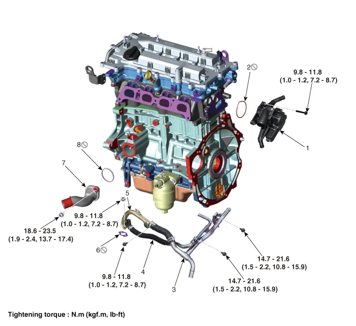
1. Integrated thermal management module (ITM)
2 . Integrated thermal management module (ITM) O-ring
3. Heater pipe B
4. Heater water hose
5. Heater pipe A
6 . Heater pipe A gasket
7 . Water inlet fitting
8 . Water inlet fitting gasket
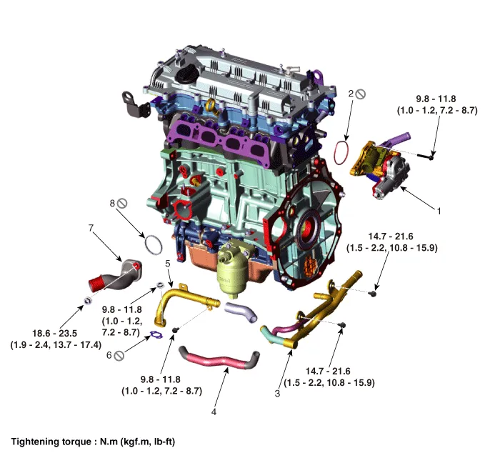
1. Integrated thermal management module (ITM)
2 . Integrated thermal management module (ITM) O-ring
3. Heater pipe B
4. Heater water hose
5. Heater pipe A
6 . Heater pipe A gasket
7 . Water inlet fitting
8 . Water inlet fitting gasket

• Be careful that static electricity and other voltages are not applied to the integrated thermal management module (ITM).
• Do not bring anything with magnetism, such as a magnet, close to the integrated thermal management module (ITM).
• When disconnecting the integrated thermal management module (ITM) connector, make sure that there is no power to the engine and other components.
• When connecting the integrated thermal management module (ITM) connector, water or oil must be completely removed from the connector and no foreign matters should be entered.
• When replacing the integrated thermal management module (ITM) connector, be sure to use the specified connector.
1.Disconnect the battery negative terminal.
2.Remove the engine room under cover.(Refer to Engine and Transaxle Assembly - "Engine Room Under Cover")
3.Drain the coolant.(Refer to Cooling System - "Coolant")
4.Remove the air duct and air cleaner assembly.(Refer to Intake and Exhaust System - "Air Cleaner")
5.Remove the battery.(Refer to Engine Electrical System - "Battery")
6.Remove the engine control module (ECM).(Refer to Engine Control/Fuel System - "Engine Control Module (ECM)")
7.Remove the battery tray.(Refer to Engine Electrical System - "Battery")
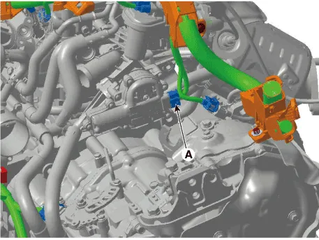
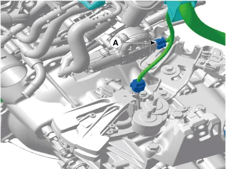
8.Disconnect the integrated thermal management module (ITM) connector (A).
9.Disconnect the radiator upper hose (A).

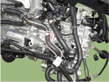
10.Disconnect the heater hose (A).
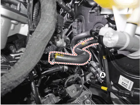
11.Disconnect the ATF warmer hose (A).
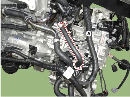
12.Remove the integrated thermal management module (ITM) (A).
Tightening torque : 9.8 - 11.8 N.m (1.0 - 1.2 kgf.m, 7.2 - 8.7 lb-ft)

13.Install in the reverse order of removal.

• Always use a new integrated thermal management module (ITM) O-ring.
14.Fill with engine coolant. (Refer to Cooling System - "Coolant")

• The coolant must be injected according to the integrated thermal management module (ITM) coolant filling method.
15.Start engine and check for leaks.

• Be careful that static electricity and other voltages are not applied to the integrated thermal management module (ITM).
• Do not bring anything with magnetism, such as a magnet, close to the integrated thermal management module (ITM).
• When disconnecting the integrated thermal management module (ITM) connector, make sure that there is no power to the engine and other components.
• When connecting the integrated thermal management module (ITM) connector, water or oil must be completely removed from the connector and no foreign matters should be entered.
• When replacing the integrated thermal management module (ITM) connector, be sure to use the specified connector.
1.Disconnect the battery negative terminal.
2.Remove the engine room under cover.(Refer to Engine and Transaxle Assembly - "Engine Room Under Cover")
3.Drain the coolant.(Refer to Cooling System - "Coolant")
4.Remove the air duct and air cleaner assembly.(Refer to Intake and Exhaust System - "Air Cleaner")
5.Remove the battery.(Refer to Engine Electrical System - "Battery")
6.Remove the engine control module (ECM).(Refer to Engine Control/Fuel System - "Engine Control Module (ECM)")
7.Remove the battery tray.(Refer to Engine Electrical System - "Battery")
8.Disconnect the integrated thermal management module (ITM) connector (A).
9.Disconnect the radiator upper hose (A).
10.Disconnect the heater hose (A).

11.Remove the integrated thermal management module (ITM) (A).
Tightening torque : 9.8 - 11.8 N.m (1.0 - 1.2 kgf.m, 7.2 - 8.7 lb-ft)
12.Install in the reverse order of removal.

• Always use a new integrated thermal management module (ITM) O-ring.
13.Fill with engine coolant. (Refer to Cooling System - "Coolant")

• The coolant must be injected according to the integrated thermal management module (ITM) coolant filling method.
14.Start engine and check for leaks.
1.Disconnect the battery negative terminal.
2.Remove the engine cover.(Refer to Engine and Transaxle Assembly - "Engine Cover")
3.Remove the engine room under cover.(Refer to Engine and Transaxle Assembly - "Engine Room Under Cover")
4.Drain the coolant.(Refer to Cooling System - "Coolant")
5.Remove the air duct and air cleaner assembly.(Refer to Intake and Exhaust System - "Air Cleaner")
6.Remove the battery.(Refer to Engine Electrical System - "Battery")
7.Remove the engine control module (ECM).(Refer to Engine Control/Fuel System - "Engine Control Module (ECM)")
8.Remove the battery tray.(Refer to Engine Electrical System - "Battery")
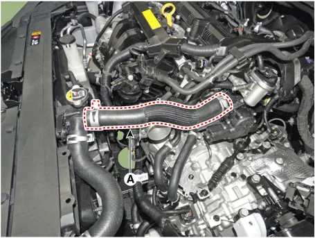
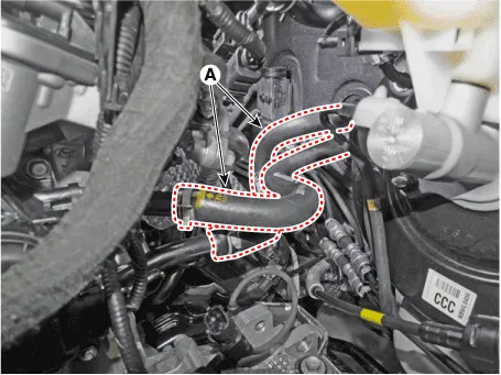
9.Disconnect the heater hoses (A).

10.Disconnect the ATF warmer hose (A).
11.Remove the integrated thermal management module (ITM).
12.Remove the intake manifold.(Refer to Intake and Exhaust System - "Intake Manifold")
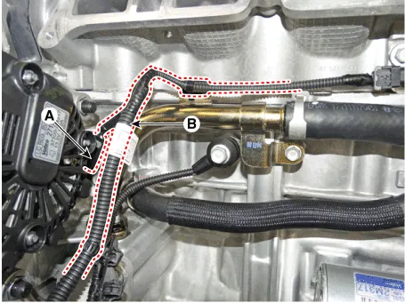
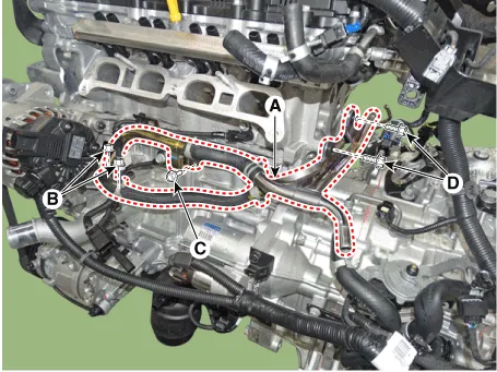
13.Disconnect the water temperature sensor (WTS) connector (A) and disconnect the wiring (B) from the heater pipe.
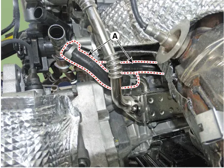
14.Disconnect the exhaust gas recirculation (EGR) cooler inlet and outlet hoses (A).
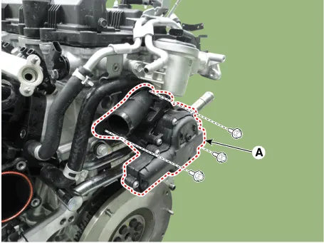
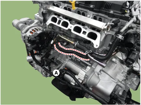
15.Disconnect the heater water hose (A).
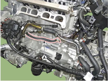
16.Remove the heater pipe (A).
Tightening torque : Nuts (B) : 9.8 - 11.8 N.m (1.0 - 1.2 kgf.m, 7.2 - 8.7 lb-ft)Bolt (C) : 9.8 - 11.8 N.m (1.0 - 1.2 kgf.m, 7.2 - 8.7 lb-ft)Bolts (D) : 14.7 - 21.6 N.m(1.5 - 2.2 kgf.m, 10.8 - 15.9 lb-ft)
17.Install in the reverse order of removal.

• Always use a new integrated thermal management module (ITM) O-ring.
• When assembling the hose, Use a product with EPDM rubber stability.
• If a hose lubricant is applied, fill the coolant after 30 minutes of assembly.
• Place the hose at the specified location of the stopper and assemble them together. The front side of stoppers should be in close contact with the hose. And then, place the clamp at the correct location.
18.Fill with engine coolant. (Refer to Cooling System - "Coolant")

• The coolant must be injected according to the integrated thermal management module (ITM) coolant filling method.
19.Start engine and check for leaks.
1.Disconnect the battery negative terminal.
2.Remove the engine cover.(Refer to Engine and Transaxle Assembly - "Engine Cover")
3.Remove the engine room under cover.(Refer to Engine and Transaxle Assembly - "Engine Room Under Cover")
4.Drain the coolant.(Refer to Cooling System - "Coolant")
5.Remove the air duct and air cleaner assembly.(Refer to Intake and Exhaust System - "Air Cleaner")
6.Remove the battery.(Refer to Engine Electrical System - "Battery")
7.Remove the engine control module (ECM).(Refer to Engine Control/Fuel System - "Engine Control Module (ECM)")
8.Remove the battery tray.(Refer to Engine Electrical System - "Battery")
9.Disconnect the heater hoses (A).
10.Remove the integrated thermal management module (ITM).
11.Remove the intake manifold.(Refer to Intake and Exhaust System - "Intake Manifold")
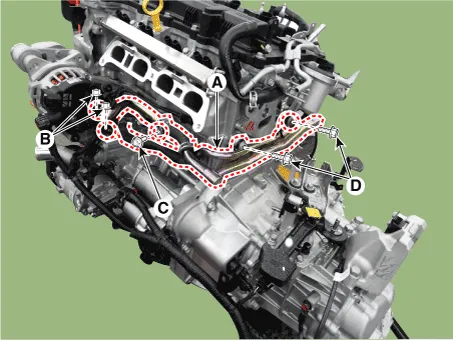
12.Disconnect the water temperature sensor (WTS) connector (A) and disconnect the wiring (B) from the heater pipe.

13.Disconnect the exhaust gas recirculation (EGR) cooler inlet and outlet hoses (A).

14.Disconnect the heater water hose (A).
15.Remove the heater pipe (A).
Tightening torque : Nuts (B) : 9.8 - 11.8 N.m (1.0 - 1.2 kgf.m, 7.2 - 8.7 lb-ft)Bolt (C) : 9.8 - 11.8 N.m (1.0 - 1.2 kgf.m, 7.2 - 8.7 lb-ft)Bolts (D) : 14.7 - 21.6 N.m(1.5 - 2.2 kgf.m, 10.8 - 15.9 lb-ft)
16.Install in the reverse order of removal.

• Always use a new integrated thermal management module (ITM) O-ring.
• When assembling the hose, Use a product with EPDM rubber stability.
• If a hose lubricant is applied, fill the coolant after 30 minutes of assembly.
• Place the hose at the specified location of the stopper and assemble them together. The front side of stoppers should be in close contact with the hose. And then, place the clamp at the correct location.
17.Fill with engine coolant. (Refer to Cooling System - "Coolant")

• The coolant must be injected according to the integrated thermal management module (ITM) coolant filling method.
18.Start engine and check for leaks.


Other information:
Hyundai Accent (HC) (2017 - 2022) Service Manual: Description and Operation
- OBD-II Review 1. Overview The California Air Resources Board (CARB) began regulation of On Board Diagnostics (OBD) for vehicles sold in California beginning with the 1988 model year. The first phase, OBD-I, required monitoring of the fuel metering system, Exhaust Gas Recirculation (EGR) system and additional emission related components.Hyundai Accent (HC) (2017 - 2022) Service Manual: Stop Lamp Switch
- Components 1. Brake pedal member assembly2. Stop lamp switch3. Brake pedal arm 4. Pedal pad - Schematic Diagram - System circuit diagram - Terminal function TerminalDescription 1IGN 2BS 3- 4B+ 5BLS 6GND - Adjustment 1.Turn ignition switch OFF and disconnect the negative (-) battery cable. 2.Remove the lower crash pad.
Categories
- Manuals Home
- Hyundai Accent Owners Manual
- Hyundai Accent Service Manual
- Questions & Answers
- Video Guides
- Useful Resources
- New on site
- Most important about car
- Privacy Policy

0.0099