Hyundai Accent (HC): Brake System / Front Disc Brake
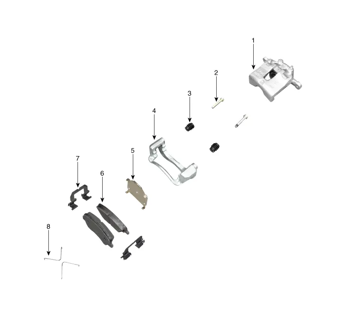
1. Caliper body
2. Guide rod pin
3. Guide rod boot
4. Caliper carrier
5. Inner pad shim
6. Brake pad
7. Pad retainer
8. Pad return spring
1.Loosen the wheel nuts slightly.Raise the vehicle, and make sure it is securely supported.
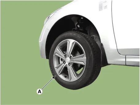
2.Remove the front wheel and tire (A) from the front hub.
Tightening torque :107.9 - 127.5 N.m (11.0 - 13.0 kgf.m, 79.6 - 94.0 lb-ft)


• Be careful not to damage the hub bolts when removing the front wheel and tire.
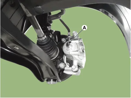
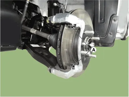
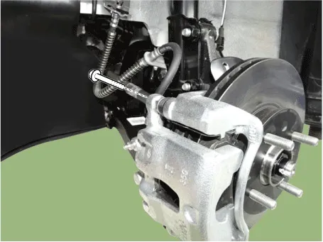
3.Disconnect the brake hose by loosening the bolt (A).
Tightening torque : 24.5 - 29.4 N.m (2.5 - 3.0 kgf.m, 18.1 - 21.7 lb-ft)
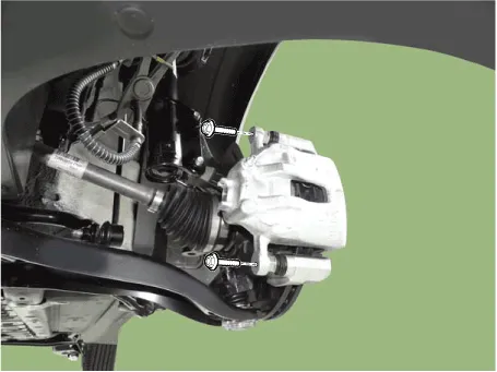
4.Remove the caliper body by loosening the guided rod bolt.
Tightening torque :21.6 - 31.4 N.m (2.2 - 3.2 kgf.m, 15.9 - 23.1 lb-ft)

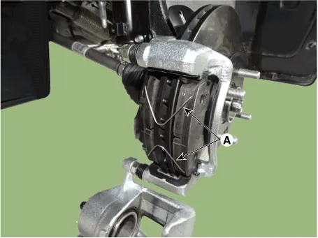
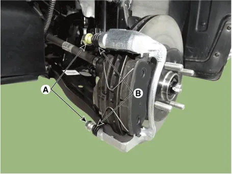
5.Remove the pad return spring (A).
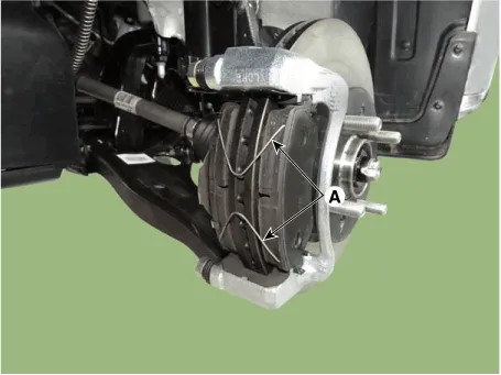

• Pad return springs must be replaced with new ones whenever pads are replaced.
• Technicians should be careful not to deform pad return springs.
• When pad return springs are deformed, it may cause improper braking, more fuel consumption.
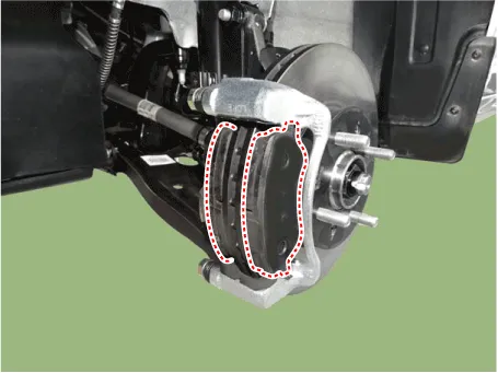
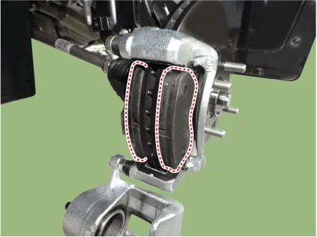
6.Remove the brake pad.
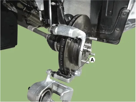
7.Remove the pad retainer (A).
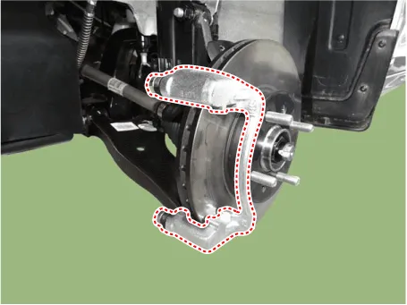
8.Remove the caliper carrier by loosening the caliper mounting bolts.
Tightening torque : 78.5 - 98.1 N.m (8.0 - 10.0 kgf.m, 57.9 - 72.3 lb-ft)
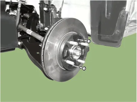
9.Loosen the screw and the remove the front disc.
Tightening torque : 4.9 - 5.9 N.m (0.5 - 0.6 kgf.m, 3.6 - 4.3 lb-ft)
1.Loosen the wheel nuts slightly.Raise the vehicle, and make sure it is securely supported.
2.Remove the front wheel and tire (A) from the front hub.


• Be careful not to damage the hub bolts when removing the front wheel and tire.
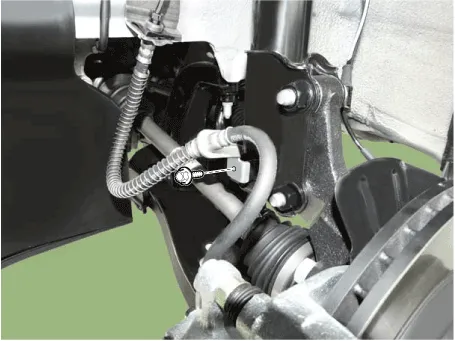
3.Loosen the mounting bolt and then remove the brake hose from the strut assembly.
4.Up the caliper body by loosening the guided rod bolt.

5.Remove the pad return spring (A).
6.Remove the brake pad.
7.Remove the pad retainer (A).
8.Replace the brake pad and pad retainer with a new one.
9.Install the pad return spring (A).


• Pad return springs must be replaced with new ones whenever pads are replaced.
• Technicians should be careful not to deform pad return springs.
• When pad return springs are deformed, it may cause improper braking, more fuel consumption.
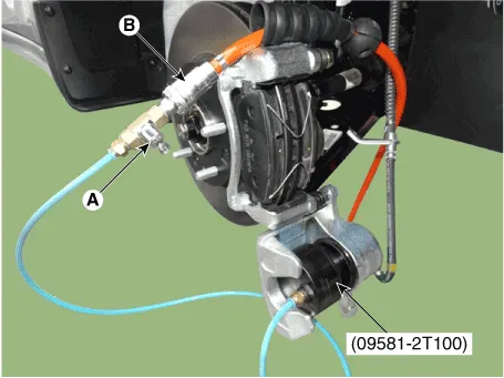
10.Use a SST (09581-2T100) when installing the brake caliper assembly.
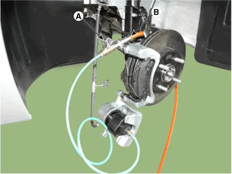

• Connect an air hose (B) to the SST after confirming that the valve of the SST is surely closed.
• Input the SST in the caliper and press the caliper piston while opening the valve of the SST slowly couter clock wise.
• Close the valve (A) of the SST and disconnect the air hose (B); then, open the valve again to get the rest of air out and remove the SST from the caliper.
11.Install the caliper body then tighten the guide rod bolt.
Tightening torque :21.6 - 31.4 N.m (2.2 - 3.2 kgf.m, 15.9 - 23.1 lb-ft)
12.Install the brake hose bracket to the front strut assembly.
Tightening torque : 8.8 - 13.7 N.m (0.9 - 1.4 kgf.m, 6.5 - 10.1 lb-ft)

13.Install the front wheel and tire (A).
Tightening torque : 107.9 - 127.5 N.m (11.0 - 13.0 kgf.m, 79.6 - 94.0 lb-ft)


• Be careful not to damage the hub bolts when installing the front wheel and tire.
1.Loosen the wheel nuts slightly.Raise the vehicle, and make sure it is securely supported.
2.Remove the front wheel and tire (A) from the front hub.
Tightening torque :107.9 - 127.5 N.m (11.0 - 13.0 kgf.m, 79.6 - 94.0 lb-ft)


• Be careful not to damage the hub bolts when removing the front wheel and tire.
3.Remove the caliper body by loosening the guided rod bolt.
4.Replace the guide rod (A) and boot (B).

• Apply the grease on the guide rod pin.Grease type : GREASE BG-1 (MG511-60)Capacity : 0.35 - 0.8 g
• If apply the grease excessively, would not be assembled the guide rod pin.
5.Install the caliper body.
Tightening torque :21.6 - 31.4 N.m (2.2 - 3.2 kgf.m, 15.9 - 23.1 lb-ft)

6.Install the front wheel and tire (A).
Tightening torque :107.9 - 127.5 N.m (11.0 - 13.0 kgf.m, 79.6 - 94.0 lb-ft)

• Be careful not to damage the hub bolts when removing the front wheel and tire.
1.Check the brake pads for wear and fade.
2.Check the brake disc for damage and cracks.
3.Remove all rust and contamination from the surface, and measure the disc thickness at 24 points, at least, of same distance (5mm) from the brake disc outer circle.
Front brake disc thickness- Standard : 22 mm (0.87 in)- Service Limit : 20.0 mm (0.79 in)Deviation : Less than 0.015 mm (0.0002 in)

4.If wear exceeds the limit, replace the discs and pad assembly left and right of the vehicle.
1.Check the pad wear. Measure the pad thickness and replace it, if it is less than the specified value.
Pad thicknessStandard : 17 mm (0.67 in)Service Limit : 8.0 mm (0.31 in)
2.Check that grease is applied, to sliding contact points and the pad and backing metal for damage.
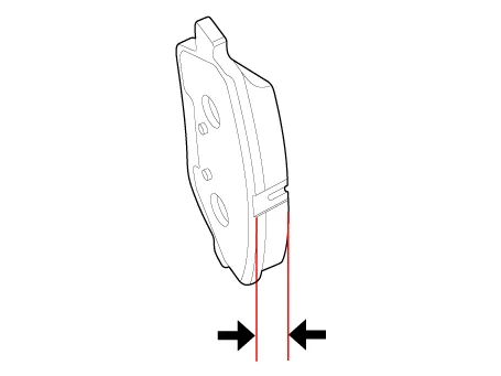
1.Place a dial gauge about 10mm (0.2 in.) from the outer circumference of the brake disc, and measure the runout of the disc.
Brake disc runoutLimit : 0.050 mm (0.0016 in.) or less (new one)

2.If the runout of the brake disc exceeds the limit specification, replace the disc, and then measure the runout again.
3.If the runout does not exceed the limit specification, install the brake disc after turning it 180° and then check the runout of the brake disc again.
4.If the runout cannot be corrected by changing the position of the brake disc, replace the brake disc.
1.To install, reverse the removal procedure.
2.Use a SST (09581-2T100) when installing the brake caliper assembly.

• Connect an air hose (B) to the SST after confirming that the valve of the SST is surely closed.
• Input the SST in the caliper and press the caliper piston while opening the valve of the SST slowly couter clock wise.
• Close the valve (A) of the SST and disconnect the air hose (B); then, open the valve again to get the rest of air out and remove the SST from the caliper.
3.After installing, bleed the brake system. (Refer to Brake System - "Brake System Bleeding")(Refer to Brake System - "ABS System Bleeding")(Refer to Brake System - "ESP System Bleeding")


Other information:
Hyundai Accent (HC) (2017 - 2022) Service Manual: Air bag - Advanced supplemental restraint system
In addition to seat belts and child restraints, the Hyundai Accent uses an Advanced Supplemental Air Bag System to help protect occupants in certain types of crashes. Air bags are not a substitute for seat belts; they are designed to work with properly worn belts. 1. Driver's front air bag 2. Passenger's front air bag 3. Side air bag 4. Curtain air bag This vehicle is equipped with an Advanced Supplemental Air Bag System for the driver's seat and front passenger's seats.Hyundai Accent (HC) (2017 - 2022) Service Manual: General Service Information
- General Service Information Protection of the VehicleAlways be sure to cover fenders, seats, and floor areas prior to beginning work. • The support rod must be inserted into the hole near the edge of the hood whenever you inspect the engine compartment to prevent the hood from falling and causing possible injury. • Make sure that the support rod has been released prior to closing the hood.
Categories
- Manuals Home
- Hyundai Accent Owners Manual
- Hyundai Accent Service Manual
- Questions & Answers
- Video Guides
- Useful Resources
- New on site
- Most important about car
- Privacy Policy

0.0102