Hyundai Accent (HC): Engine Mechanical System / Intake And Exhaust System
Contents:
Air Cleaner
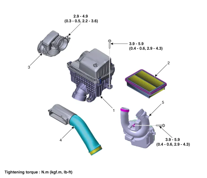
1. Air cleaner assembly
2. Air cleaner element
3. Air intake hose
4. Air duct
5. Resonator
1.Disconnect the battery negative terminal.
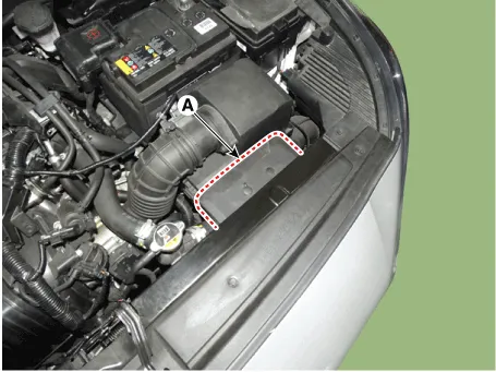
2.Remove the air duct (A).
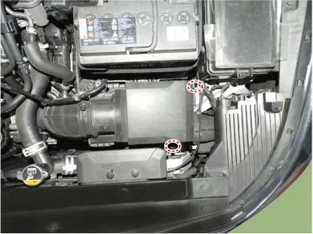
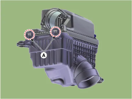
3.Remove the air cleaner assembly.
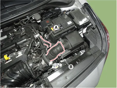
(1)Disconnect the air flow sensor (AFS) connector (A).
(2)Disconnect the breather hose B (B).
(3)Disconnect the intake air hose (C).
Tightening torque : 2.9 - 4.9 N.m (0.3 - 0.5 kgf.m, 2.2 - 3.6 lb-ft)
(4)Remove the air cleaner assembly (D).
Tightening torque : 3.9 - 5.9 N.m (0.4 - 0.6 kgf.m, 2.9 - 4.3 Ib-ft)

4.Install in the reverse order of removal.
1.Open the air cleaner cover by unhooking the clamps.

2. Replace the air cleaner element (A) with a new one.
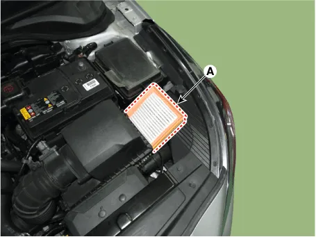

‚ÄĘ If there are foreign substances inside the air cleaner assembly, wipe the inside of the air cleaner assembly and then replace the air cleaner element.
3.Close the air cleaner cover by hooking the clamps.

‚ÄĘ Install the air cleaner cover, insert the hinge (A) and fill the clamp.
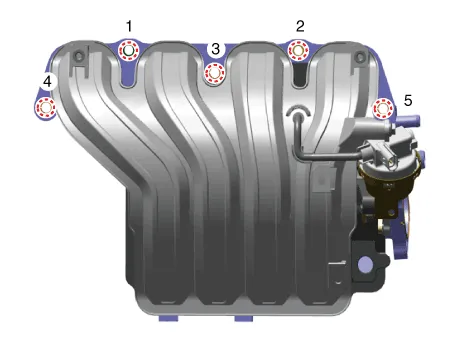
Intake Manifold
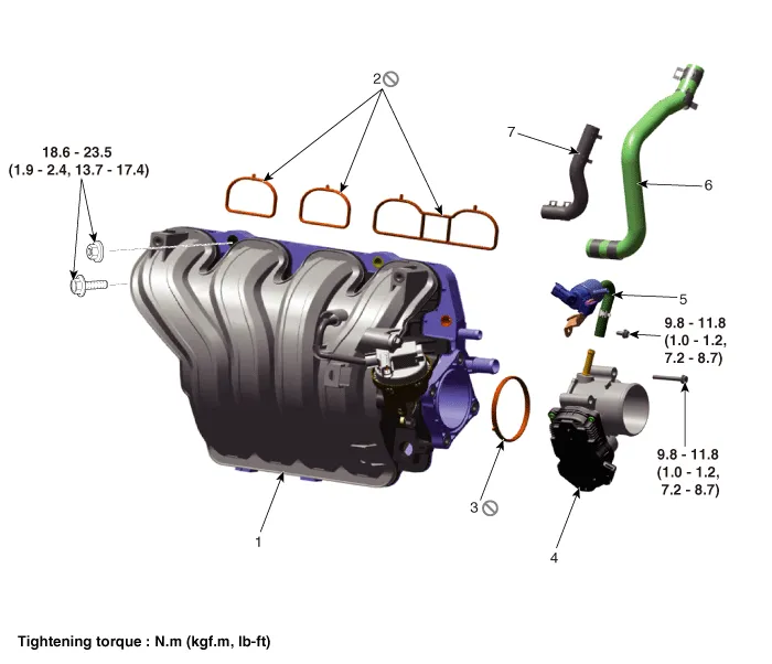
1. Intake manifold
2. Intake manifold gasket
3. Electronic throttle body (ETC) gasket
4. Electronic throttle body (ETC)
5. Purge control solenoid valve (PCSV) and hose
6. EGR hose
7. Vacuum hose
1.Disconnect the battery negative terminal.
2.Remove the engine cover.(Refer to Engine and Transaxle Assembly System - "Engine cover")
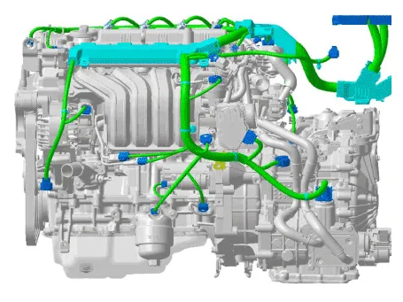
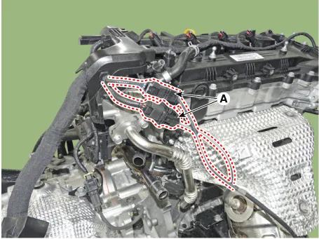
3.Remove the engine wire harness connectors and wire harness clamps from cylinder head and the intake manifold.
4.Disconnect the intake air hose.
(1)Disconnect the breather hose B (A).
(2)Disconnect the intake air hose (B).
Tightening torque : 2.9 - 4.9 N.m (0.3 - 0.5 kgf.m, 2.2 - 3.6 lb-ft)
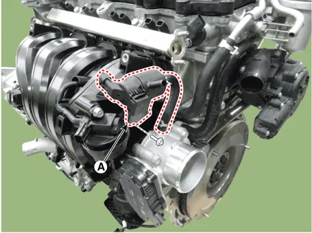
5.Remove the Purge control solenoid valve (PCSV) bracket (A) from intake manifold.
Tightening torque :9.8 - 11.8 N.m (1.0 - 1.2 kgf.m, 7.2 - 8.7 lb-ft)
6.Remove the Electronic Throttle Control (ETC) module.(Refer to Engine Control/ Fuel System - "ETC (Electronic Throttle Control")
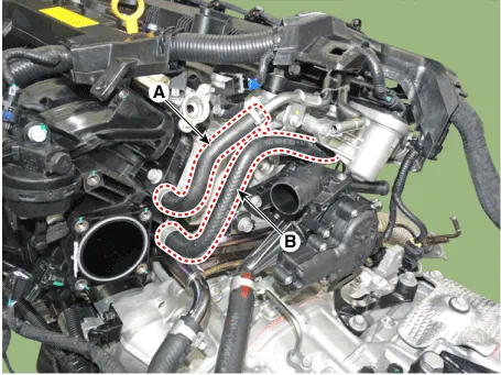
7.Disconnect the vacuum hose (A) and EGR hose (B).
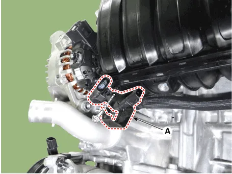
8.Remove the wiring bracket (A).
Tightening torque : 6.9 - 9.8 N.m (0.7 - 1.0 kgf.m, 5.1 - 13.7 lb-ft)
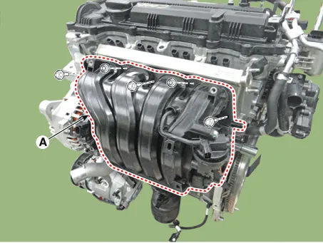
9.Remove the Intake Manifold (A).
Tightening torque : 18.6 - 23.5 N.m (1.9 - 2.4 kgf.m, 13.7 - 17.4 lb-ft)
10.Install in the reverse order of removal.

‚ÄĘ When installing, replace with new gaskets.
‚ÄĘ When installing the intake manifold, tighten sequence shown.
Exhaust Manifold
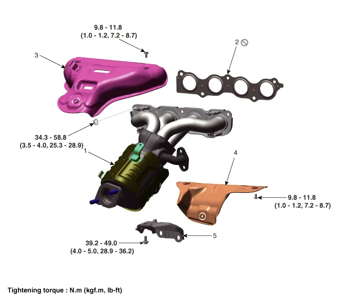
1. Exhaust manifold
2. Exhaust manifold gasket
3. Exhaust manifold heat protector A
4. Exhaust manifold heat protector B
5. Exhaust manifold stay
1.Disconnect the battery negative terminal.
2.Remove the engine cover.(Refer to Engine and Transaxle Assembly System - "Engine cover")
3.Remove the engine room under cover.(Refer to Engine and Transaxle Assembly System - "Engine Room Under Cover")
4.Disconnect the front oxygen sensor connectors (A).
5.Remove the front muffler. (Refer to Intake and Exhaust Manifold - "Front Muffler")
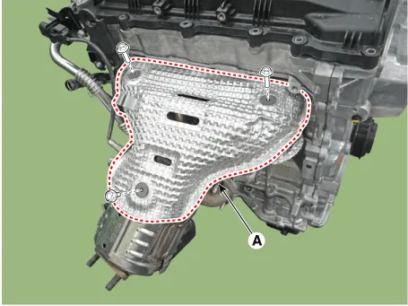
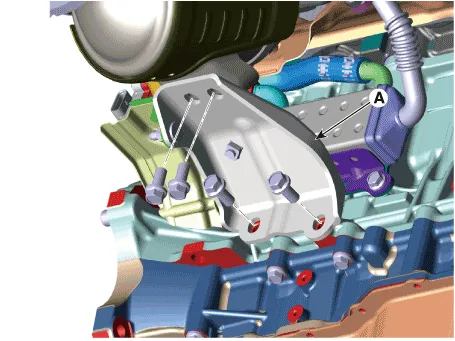
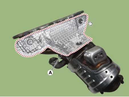
6.Remove the exhaust manifold heat protector A (A).
Tightening torque : 9.8 - 11.8 N.m (1.0 - 1.2 kgf.m, 7.2 - 8.7 lb-ft)
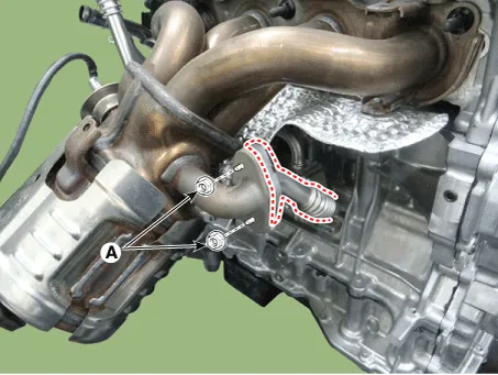
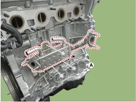
7.Remove the EGR cooler mounting nuts (A).
Tightening torque :18.6 - 23.5 N.m (1.9 - 2.4 kgf.m, 13.7 - 17.4 lb-ft)
8.Remove the exhaust manifold stay (A).
Tightening torque :39.2 - 49.0 N.m (4.0 - 5.0 kgf.m, 28.9 - 36.2 lb-ft)
9.Remove the engine mounting support bracket.(Refer to Engine and Transaxle Assembly - "Engine Mounting")
10.With the jack, lower the engine to get enough space for removing the exhaust manifold.
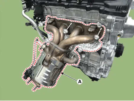
11.Remove the exhaust manifold (A).
Tightening torque :34.3 - 39.2 N.m (3.5 - 4.0 kgf.m, 25.3 - 28.9 lb-ft)
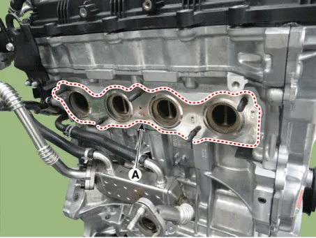
12.Remove the exhaust manifold gasket (A).
13.Remove the exhaust manifold heat protector B (A).
Tightening torque :9.8 - 11.8 N.m (1.0 - 1.2 kgf.m, 7.2 - 8.7 lb-ft)
14.Install in the reverse order of removal.

‚ÄĘ When installing the exhaust manifold, with a new gasket.
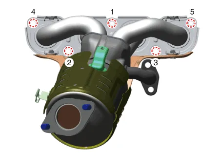
‚ÄĘ When installing the exhaust manifold, tighten the nuts with pre-torque first and then tighten the nuts with specified torque in the sequence shown.
‚ÄĘ When installing the exhaust manifold stay, tighten the nuts with pre-torque first and then tighten the nuts with specified torque in the sequence shown.

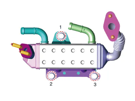
EGR Cooler
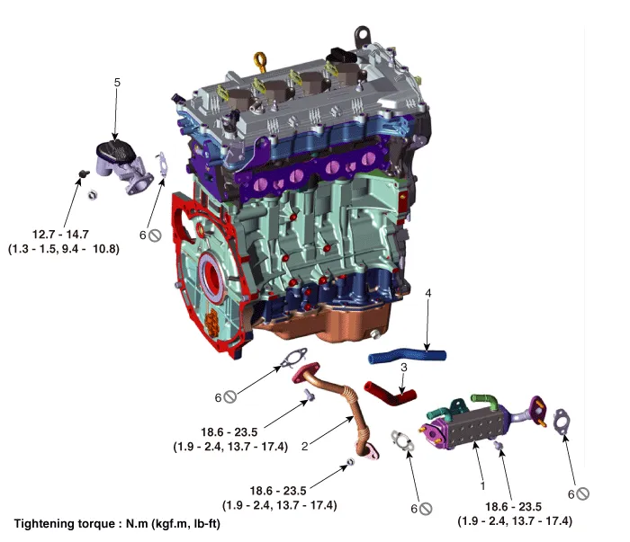
1. EGR cooler
2. EGR cooler pipe B
3. EGR cooler outlet hose
4. EGR cooler inlet hose
5. EGR valve
6. Gasket
1.Disconnect the battery negative terminal.
2.Remove the engine cover.(Refer to Engine and Transaxle Assembly - "Engine Cover")
3.Remove the engine room under cover.(Refer to Engine and Transaxle Assembly - "Engine Room Under Cover")
4.Loosen the drain plug and drain the coolant. (Refer to Cooling System - "Coolant")
5.Remove the exhaust manifold.(Refer to Intake And Exhaust System - "Exhaust Manifold")
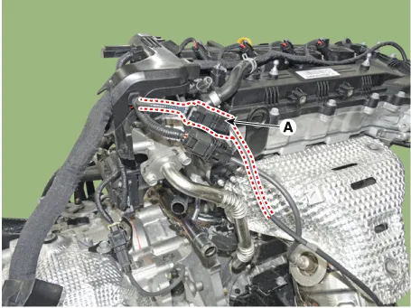
6.Disconnect the EGR cooler inlet and outlet hoses (A).

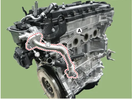
7.Remove the EGR cooler pipe B (A).
Tightening torque :18.6 - 23.5 N.m (1.9 - 2.4 kgf.m, 13.7 - 17.4 lb-ft)
8.Remove the EGR cooler (A).
Tightening torque :18.6 - 23.5 N.m (1.9 - 2.4 kgf.m, 13.7 - 17.4 lb-ft)
9.Install in the reverse order of removal.

‚ÄĘ When installing, replace with new gaskets.
‚ÄĘ When installing the EGR cooler, tighten the sequence shown.
10.Fill the radiator with coolant.(Refer to Cooling system - "Coolant")

‚ÄĘ The coolant must be injected according to the integrated thermal management module (ITM) coolant filling method.
Muffler
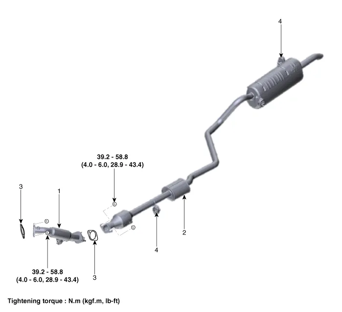
1. Front muffler
2. Center muffler & Rear muffler
3. Gasket
4. Hanger
1.Disconnect the battery negative terminal.
2.Disconnect the oxygen sensor connector (A) and then disconnect from bracket.
3.Remove the front muffler (A).
Tightening torque :39.2 - 58.8 N.m (4.0 - 6.0 kgf.m, 28.9 - 43.4 lb-ft)

4.Install in the reverse order of removal.

‚ÄĘ When installing, replace with new gaskets.
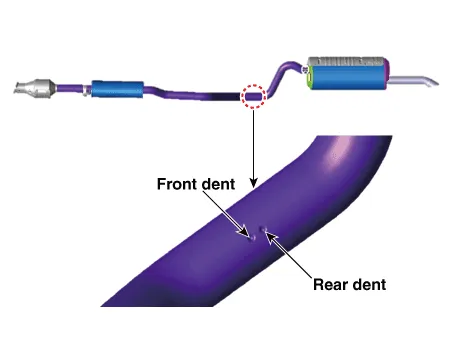
1.Check that the clamping part of the main muffler assembly is damaged or deformed.

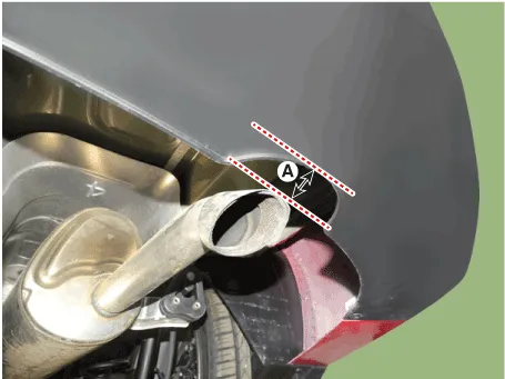
2.Record the gap (A) between the tail pipe and the rear bumper.

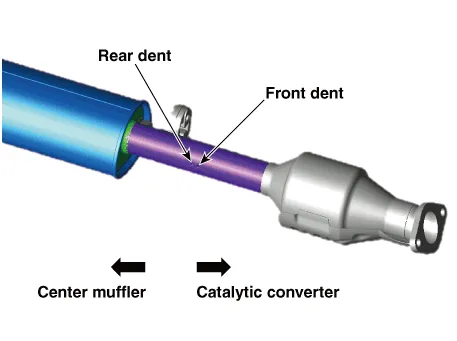
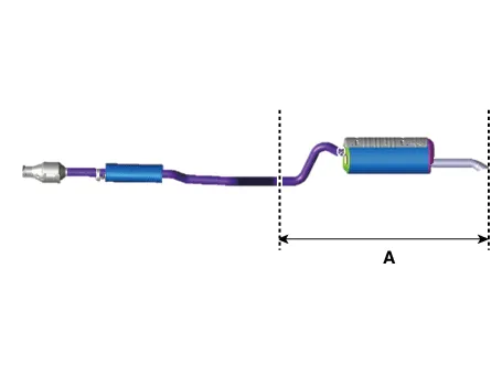
3.Cut the main muffler as indicated below.

‚ÄĘ Cut the part where the clamp is to be tightened while the muffler is installed in the vehicle.
‚Äď Cut the muffler pipe marked with the rear dent.


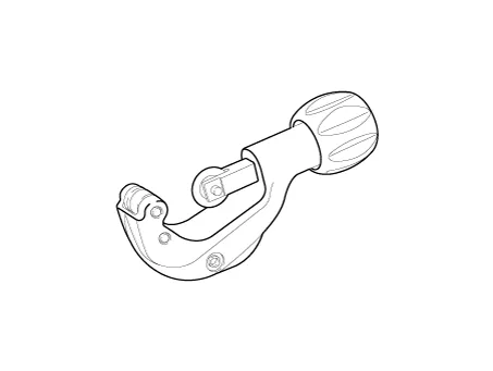
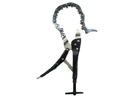
‚ÄĘ Use a pipe cutter or chain pipe cutter to make sure the cutting surface is smooth and even.


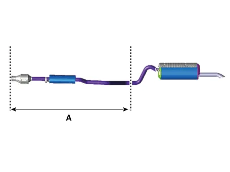
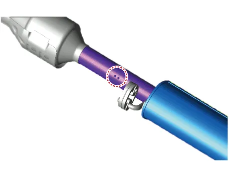
4.Replace the catalytic converter and center muffler (A) as shown in the image below.(Refer to the clamp installation procedures)

1.Check that the clamping part of the main muffler assembly is damaged or deformed.

2.Record the gap (A) between the tail pipe and the rear bumper.

3.Cut the main muffler as the indicated below.

‚ÄĘ Cut the part where the clamp is to be tightened while the muffler is installed in the vehicle.
‚Äď Cut the muffler pipe marked with the rear dent.

‚ÄĘ Use a pipe cutter or chain pipe cutter to make sure the cutting surface is smooth and even.
4.Replace the catalytic converter and center muffler (A) as shown in the image below.(Refer to the clamp installation procedures)
1.Check that the clamping part of the main muffler assembly is damaged or deformed.
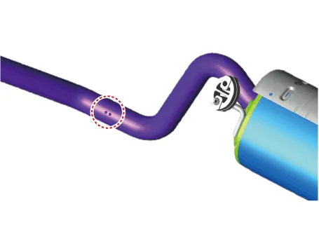
2.Record the gap (A) between the tail pipe and the rear bumper.

3.Cut the main muffler as indicated below.

‚ÄĘ Cut the part where the clamp is to be tightened while the muffler is installed in the vehicle.
‚Äď Cut the muffler pipe marked with the rear dent.

4.Cut the center muffler as indicated below.

‚ÄĘ Cut the part where the clamp is to be tightened while the muffler is installed in the vehicle.
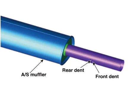
‚Äď Cut the muffler pipe marked with the front dent.
‚Äď Cut the A/S muffler marked with the rear dent.

‚ÄĘ To prevent leaks, remove the rust on the clamping part or the burr on the cutting part.
‚ÄĘ Cut the pipe vertically.

‚ÄĘ Use a pipe cutter or chain pipe cutter to make sure the cutting surface is smooth and even.


5.Replace the center muffler (A) as shown in the image below.(Refer to the clamp installation procedures)

1.Check that the clamping part of the main muffler assembly is damaged or deformed.

2.Record the gap (A) between the tail pipe and the rear bumper.
3.Cut the main muffler as indicated below.

‚ÄĘ Cut the part where the clamp is to be tightened while the muffler is installed in the vehicle.
‚Äď Cut the muffler pipe marked with the front dent.


‚ÄĘ Use a pipe cutter or chain pipe cutter to make sure the cutting surface is smooth and even.


4.Replace the main muffler (A) as shown in the image below.(Refer to the clamp installation procedures)
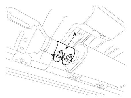
1.Put the clamp (A) between the cutting parts of the pipse and tighten the clamp lightly, not completely.

2.Tighten the catalytic converter and the center muffler with specified torque.
Tightening torque :40.0 - 60.0 N.m (4.1 - 6.1 kgf.m, 29.5 - 44.3 lb-ft)
3.Compare the gap between the tail pipe(or tail trim) and the rear bumper with the record measured before removing the center muffler assembly.

‚ÄĘ If the tail pipe position is different from the initial position, the bumper may be damaged by the pipe noise and heat which arise from the interference between the tail pipe and the rear bumper.
4.Do not tighten the clamp by turning it once. Tighten the clamp nuts with the specified torque by alternately turning them a couple of times.
Tightening torque :18.0 - 24.0 N.m (1.8 - 2.5 kgf.m, 13.3 - 17.7 lb-ft)

‚ÄĘ Do not reuse the clamp that was tightened completely. If reused, the clamp may cause leaks.
1.Tighten the main muffler and the center muffler with specified torque.
Tightening torque :40.0 - 60.0 N.m (4.1 - 6.1 kgf.m, 29.5 - 44.3 lb-ft)

‚ÄĘ If the tail pipe position is different from the initial position, the bumper may be damaged by the pipe noise and heat which arise from the interference between the tail pipe and the rear bumper.
2.Do not tighten the clamp by turning it once. Tighten the clamp nuts with the specified torque by alternately turning them a couple of times.
Tightening torque :18.0 - 24.0 N.m (1.8 - 2.5 kgf.m, 13.3 - 17.7 lb-ft)

‚ÄĘ The gap between the head of the clamp bolt and the fuel tank shall range from 35 mm (1.3780 in) to 40 mm (1.5748 in).
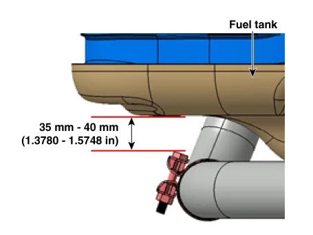
‚ÄĘ Do not reuse the clamp that was tightened completely. If reused, the clamp may cause leaks.


Other information:
Hyundai Accent (HC) (2017 - 2022) Service Manual: Specifications
- Specifications DescriptionSpecificationsLimit General TypeIn-line, DOHC „ÄÄ Number of cylinders4 „ÄÄ Bore75.60 mm (2.9764 in) „ÄÄ Stroke89.0 mm (3.5039 in.)„ÄÄ Total displacement1,598 cc (97.52 cu.in)„ÄÄ Compression ratio11.2 ¬Ī 0.2 : 1„ÄÄ Firing order1-3-4-2 „ÄÄ Valve timing Intake valveOpensBTDC 42¬į - ATDC 38¬į „ÄÄ ClosesABDC 7¬į - ABDC 87¬į „ÄÄ Exhaust valveOpensBBDC 43¬į - ABDC 2¬į „ÄÄ ClosesATDC 0¬į - ATDC 45¬į „ÄÄ Cylinder head Flatness of gasket surfaceLess than 0.Hyundai Accent (HC) (2017 - 2022) Service Manual: Changing Tires
WARNING A vehicle can slip or roll off of a jack causing serious injury or death to you or those nearby. Take the following safety precautions: Never place any portion of your body under a vehicle that is supported by a jack. Your Hyundai Accent must be supported only at the correct jacking points and must never be relied on as a ‚Äústand.‚ÄĚ NEVER attempt to change a tire in the lane of traffic.
Contents
Categories
- Manuals Home
- Hyundai Accent Owners Manual
- Hyundai Accent Service Manual
- Questions & Answers
- Video Guides
- Useful Resources
- New on site
- Most important about car
- Privacy Policy

0.0089