Hyundai Accent (HC): Engine Mechanical System / Engine And Transaxle Assembly
Contents:
Engine Cover
1.Remove the engine cover (A).
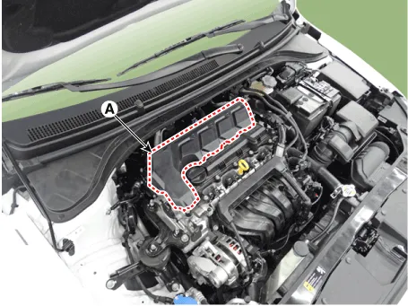
2.Installation is reverse order of removal
Engine Room Under Cover
1.Remove the engine room under cover (A).
Tightening torque :7.8 - 11.8 N.m (0.8 - 1.2 kgf.m, 5.8 - 8.7 lb-ft)
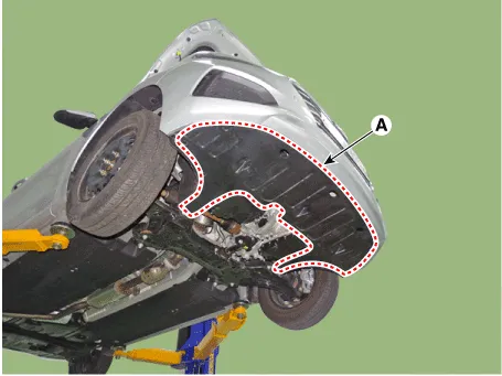
2.Installation is reverse order of removal.
Engine Mounting
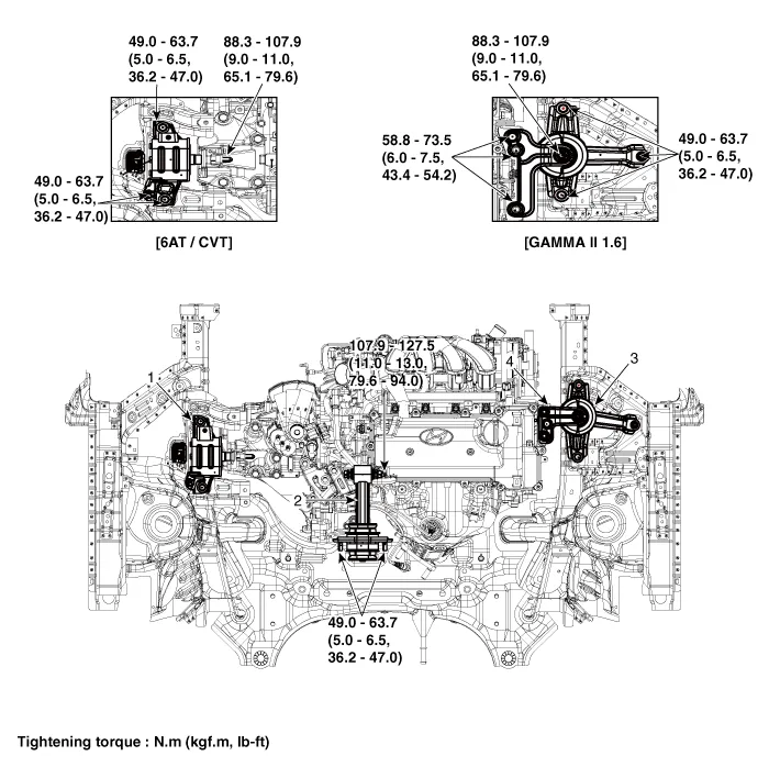
1. Transaxle mounting bracket
2. Roll road bracket
3. Engine mounting bracket
4. Engine mounting support bracket
1.Remove the engine room under cover.(Refer to Engine and Transaxle Assembly - "Engine Room Under Cover")
2.Install the jack to the edge of oil pan

• Insert the rubber block between jack and oil pan.
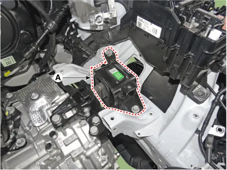
3.Remove the engine mounting support bracket (A).
Tightening torque Nut (B) : 88.3 - 107.9 N.m (9.0 - 11.0 kgf.m, 65.1 - 79.6 lb-ft)Bolt, Nuts (C) : 58.8 - 73.6 N.m (6.0 - 7.5 kgf.m, 43.4 - 54.2 lb-ft)
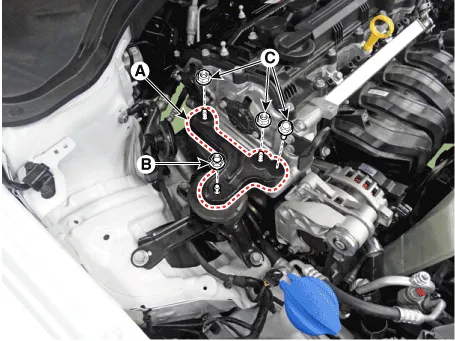
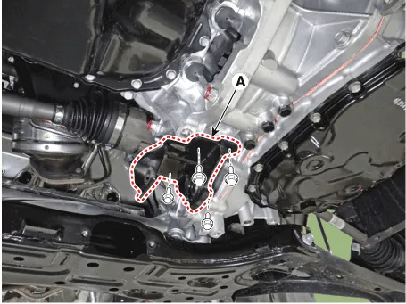
4.Remove the engine mounting bracket (A).
Tightening torque :49.0 - 63.7 N.m (5.0 - 6.5 kgf.m, 36.2 - 47.0 lb-ft)
5.Install in the reverse order of removal.
1.Disconnect the battery negative terminal.
2.Remove the engine room under cover.(Refer to Engine and Transaxle Assembly - "Engine Room Under Cover")
3.Remove the air duct and air cleaner assembly.(Refer to Intake and Exhaust System - "Air Cleaner")
4.Remove the battery.(Refer to Engine Electrical System - "Battery")
5.Remove the engine control module (ECM).(Refer to Engine Control/Fuel System - "Engine Control Module (ECM)")
6.Remove the battery tray.(Refer to Engine Electrical System - "Battery")
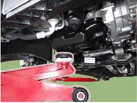
7.Install the jack under the transaxle to support it.

• Insert the rubber block between jack and transaxle.
8.Remove the service cover (A).
9.Remove the transaxle support bracket mounting bolts (A).
Tightening torque :88.3 - 107.9 N.m (9.0 - 11.0 kgf.m, 65.1 - 79.6 lb-ft)
10.Remove the transaxle mounting bracket (A).
Tightening torque : 49.0 - 63.7 N.m (5.0 - 6.5 kgf.m, 36.2 - 47.0 lb-ft)
11.Install in the reverse order of removal.
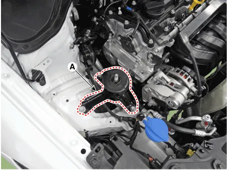
1.Remove the engine room under cover.(Refer to Engine and Transaxle Assembly - "Engine Room Under Cover")
2.Remove the roll rod bracket (A).
Tightening torqueBolt (B) : 107.9 - 127.5 N.m (11.0 - 13.0 kgf.m, 79.6 - 94.0 lb-ft)Bolts (C) : 49.0 - 63.7 N.m (5.0 - 6.5 kgf.m, 36.2 - 47.0 lb-ft)
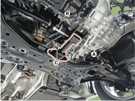
3.Remove the roll rod suppot bracket (A).
Tightening torque :49.0 - 68.6 N.m (5.0 - 7.0 kgf.m, 36.2 - 50.6 lb-ft)
4.Install in the reverse order of removal.
Engine And Transaxle Assembly
![]()
• Use fender covers to avoid damaging painted surfaces.
• To avoid damage, unplug the wiring connectors carefully while holding the connector portion.
![]()
• Mark all wiring connector and hoses to avoid misconnection.
1.Disconnect the battery negative terminal.
2.Remove the engine cover(Refer to Engine and Transaxle Assembly - "Engine Cover")
3.Remove the engine room under cover.(Refer to Engine and Transaxle Assembly - "Engine Room Under Cover")
4.Drain the coolant.(Refer to Cooling System - "Coolant")
5.Recover the refrigerant and then remove the high pressure pipe and low pressure pipe.(Refer to Heating, Ventilation Air conditioning - "Compressor")
6.Remove the air duct and air cleaner assembly.(Refer to Intake and Exhaust System - "Air Cleaner")
7.Remove the battery.(Refer to Engine Electrical System - "Battery")
8.Remove the engine control module (ECM).(Refer to Engine Control/Fuel System - "Engine Control Module (ECM)")
9.Remove the battery tray.(Refer to Engine Electrical System - "Battery")
10.Disconnect the radiator upper hose (A).
![]()
11.Disconnect the radiator lower hose (A).
![]()
12.Disconnect the brake booster vacuum hose (A).
![]()
13.Disconnect the heater hoses (A).
![]()
14.Remove the transaxle wire harness connectors and control cable from the transaxle.(Refer to Intelligent Variable Transmission (IVT) System - "Intelligent Variable Transmission (IVT)")(Refer to Manual Transaxle System - "Manual Transaxle")
15.Disconnect the fuel hose (A) and purge control solenoid valve (PCSV) hose (B).
![]()
16.Disconnect the wiring connectors and harness clamps and remove the connector brackets around the engine and transaxle assembly.
![]()
![]()
17.Disconnect the battery positive wirings (A)
![]()
18.Remove the front muffler.(Refer to Intake and Exhaust System - "Muffler")
19.Remove the roll rod bracket (A).
Tightening torque Bolt (B) : 107.9 - 127.5 N.m (11.0 - 13.0 kgf.m, 79.6 - 94.0 lb-ft)Bolts (C) : 49.0 - 63.7 N.m (5.0 - 6.5 kgf.m, 36.2 - 47.0 lb-ft)
![]()
20.Remove the roll rod support bracket (A).
Tightening torque : 49.0 - 68.6 N.m (5.0 - 7.0 kgf.m, 36.2 - 50.6 lb-ft)
![]()
21.Remove the steering U-joint mounting bolt.(Refer to Steering System - "Steering Gear Box")
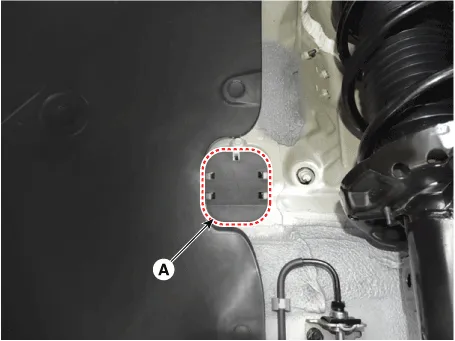
22.Remove the sub frame.(Refer to Suspension System - "Sub Frame")
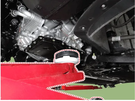
23.Support the Engine and Transaxle Assembly with a floor jack.
24.Remove the engine mounting support bracket (A).
Tightening torque :Bolt (B) : 88.3 - 107.9 N.m (9.0 - 11.0 kgf.m, 65.1 - 79.6 lb-ft)Bolt, Nuts (C) : 58.8 - 73.6 N.m (6.0 - 7.5 kgf.m, 43.4 - 54.2 lb-ft)
![]()
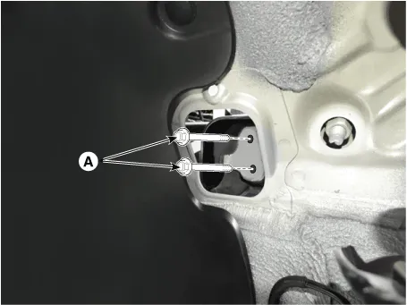
25.Disconnect the engine ground (A).
Tightening torque : 10.8 - 13.7 N.m (1.1 - 1.4 kgf.m, 8.0 - 10.1 lb-ft)
![]()
26.Remove the service cover (A).
![]()
27.Remove the transaxle support bracket mounting bolts (A).
Tightening torque : 88.3 - 107.9 N.m (9.0 - 11.0 kgf.m, 65.1 - 79.6 lb-ft)
![]()
28.Disconnect the transaxle ground cable (A).
Tightening torque : 10.8 - 13.7 N.m (1.1 - 1.4 kgf.m, 8.0 - 10.1 lb-ft)
![]()
29.Remove the engine and transaxle assembly by lifting vehicle.
![]()
![]()
• Before removing the engine and transaxle assembly, make sure hoses and wire connectors are disconnected.
• When removing the engine and transaxle assembly, be careful not to damage any surrounding parts or body components.
1.Install in the reverse order of removal.
2.Fill with engine coolant. (Refer to Cooling System - "Coolant")
![]()
• The coolant must be injected according to the integrated thermal management module (ITM) coolant filling method.
Perform the following• Refill the transaxle with fluid.
• Inspect for fuel leakage.
– After assemble the fuel line, turn on the ignition switch (do not operate the starter) so that the fuel pump runs for approximately two seconds and fuel line pressurizes.
– Repeat this operation two or three times, then check for fuel leakage at any point in the fuel line.
• Clean battery posts and cable terminals with sandpaper assemble them, then apply grease to prevent corrosion.


Other information:
Hyundai Accent (HC) (2017 - 2022) Service Manual: Repair procedures
- Refrigerant System Service Basics Refrigerant Identification • Do not mix R-1234yf in the vehicle with other refrigerant, such as R-134a and etc. • Use only service equipment that is U.L-listed and is certified to meet the requirements of SAE standards to recover and recycle R-1234yf from the air conditioning system. Do not use service equipment for the other refrigerant, such as R-134a and etc.Hyundai Accent (HC) (2017 - 2022) Service Manual: Warning and Indicator Lights
Information Make sure that all warning lights are OFF after starting the engine. If any light remains ON, it indicates a condition that requires attention. Air Bag Warning Light This warning light illuminates: When the ignition switch is turned to the ON position. - It illuminates for approximately 6 seconds and then turns off. When there is a malfunction in the Supplemental Restraint System (SRS).
Contents
Categories
- Manuals Home
- Hyundai Accent Owners Manual
- Hyundai Accent Service Manual
- Questions & Answers
- Video Guides
- Useful Resources
- New on site
- Most important about car
- Privacy Policy

0.011