Hyundai Accent (HC): Intelligent Variable Transmission (IVT) System (Continuously Variable Transmission) / IVT Control System
Contents:
- Description and Operation
- Repair procedures
- Transmission Control Module (TCM)
- E-Module
- Driven Pulley Pressure Sensor
- Driven Pulley Speed Sensor
- Position Switch
- Shift Lever
- Shift Cable
- Parking Sprag
- Parking Rod Cam
Description and Operation
Repair procedures
1.Transmission Control Module (TCM) adaptive values learning : When shift shock has occurred or parts related with the Intelligent Variable Transmission (IVT) has been replaced, TCM learning should be performed.
2.In the following case, TCM learning is required. 1) IVT replacement 2) TCM upgrade or replacement
1.P range learning (learning condition : Intelligent Variable Transmission Fluid (IVTF) temperature : 30 - 90°C (86 - 194°F), shift lever P range, brake off)1) Start the engine after checking for the IVTF temperature in state of IG ON.2) Engine RPM will rise to approximately 1000 rpm after starting the engine.3) After 30 seconds to 2 minutes, the learning is completed when the engine RPM reaches the IDLE level.(Learning completion can be confirmed from the "Sensor Data" of diagnotic tool )

• Do not operate the shift lever, step on the accelerator pedal or brakes during P-step learning.(If it is operated during learning, perform it again after turning off the ignition switch.)
Transmission Control Module (TCM)
![]()
1. Transmission control module (TCM)
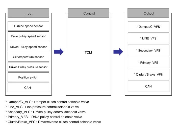
• Monitors the vehicle's operating conditions to determine the optimal gear setting.
• Performs a gear change if the current gear setting differs from the identified optimal gear setting.
• Determines the need for torque converter clutch activation and engages the clutch accordingly.
• Calculates the optimal line pressure level by constantly monitoring the torque level and adjusts the pressure accordingly.
• Diagnoses the faults and failures for Intelligent Variable Transmission (IVT) .
![]()
![]()
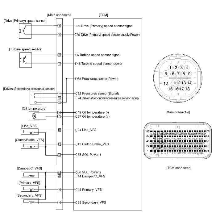
| Connector [A] | Connector [B] | ||
| Pin | Description | Pin | Description |
| A5 | Driven (Secondary) speed sensor signal | B1 | Ground |
| A6 | Turbine speed sensor signal | B2 | Ground |
| A24 | Line pressure control solenoid valve (Line_VFS) | B3 | Battery power |
| A26 | Drive (Primary) speed sensor signal | B4 | Ground |
| A27 | Oil temperature (+) | B26 | IGN. |
| A29 | Position sensor (Ground) | B45 | CAN (Low) |
| A32 | Pressures sensor (Signal) | B60 | Battery |
| A43 | Drive/reverse clutch control solenoid valve (Clutch/Brake_VFS) | B62 | CAN (High) |
| A44 | Damper clutch control solenoid valve (Damper/C_VFS) | ||
| A45 | Drive pulley control solenoid valve (Primary_VFS) | ||
| A46 | Turbine speed sensor (Power) | ||
| A47 | Position sensor (Power) | ||
| A48 | Position sensor (S1) | ||
| A49 | Oil temperature (-) | ||
| A55 | Sports mode down switch | ||
| A57 | Sports mode up switch | ||
| A65 | Driven pulley control solenoid valve (Secondary_VFS) | ||
| A68 | Pressures swnsor (Power) | ||
| A69 | Driven (Secondary) speed sensor supply (Power) | ||
| A74 | Driven (Secondary) pressures sensor signal | ||
| A76 | Drive (Primary) speed sensor supply(Power) | ||
| A85 | Solenoid valve 1 (Power) | ||
| A86 | Solenoid valve 2 (Power) | ||
| A93 | Position sensor (S2) | ||
| A98 | Sports mode select switch | ||
1.Transmisson Control Module (TCM) ground circuit test : Measure the resistance between TCM and chassis ground. (Inspect the terminal connected to the chassis ground with the back of harness connector as the inspection point of TCM side.)
Specification : Below 1Ω
2.TCM connector test : Disconnect the TCM connector and visually check the ground terminals on TCM side and harness side for bent pins or poor contact pressure.
3. If problem is not found in Steps 1 and 2, the TCM could be faulty. If so, replace the TCM with a new one, and then check the vehicle again. If the vehicle operates normally then the problem was likely with the TCM.
4.Reinspection of original TCM : Install the original TCM (probably broken) into a known-good vehicle and check the vehicle. If the problem occurs again, replace the original TCM with a new one.If the problem does not reoccur, this is an intermittent problem and other part may be faulty.
1.Perform the oil pressure characteristics backup procedure using the diagnotic tool when replacing with a new TCM.
![]()
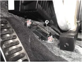
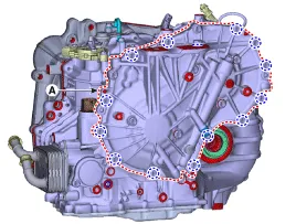
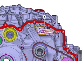
2.Remove the battery.(Refer to Body Electrical System - "Battery")
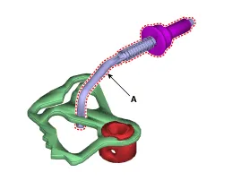
3.Disconnect the TCM connectors (A).
Tightening torque : 9.8 - 11.8 N.m (1.0 - 1.2 kgf.m, 7.2 - 8.7 lb-ft)
![]()
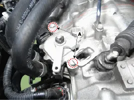
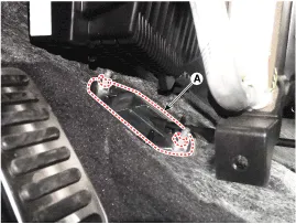
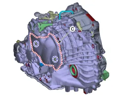
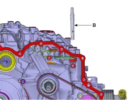
4.Remove the bolts (A) and nut (B)
5.Remove the TCM (C).
Tightening torque : 9.8 - 11.8 N.m (1.0 - 1.2 kgf.m, 7.2 - 8.7 lb-ft)
![]()
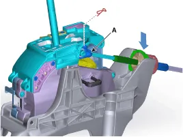
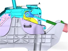
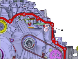
6.Loosen the mounting nuts and then removing the TCM (A) from the bracket.
Tightening torque : 9.8 - 11.8 N.m (1.0 - 1.2 kgf.m, 7.2 - 8.7 lb-ft)
![]()
1.To install reverse the removal procedures.
2.Perform the oil pressure characteristics input procedure using the diagnotic tool when replacing with a new TCM.
![]()
3.Perform the ECM-related procedures. (Refer to Engine Control / Fuel System - "Engine Control Module")
E-Module
Drive Pulley Speed Sensor
| Item | Specification |
| Type | Hall sensor |
| Output voltage (V) | High : 1.18 - 1.68 (Nor : 1.4) |
| Low : 0.59 - 0.84 (Nor : 0.7) |
Turbine Speed Sensor
| Item | Specification |
| Type | Hall sensor |
| Output voltage (V) | High : 1.18 - 1.68 (Nor : 1.4) |
| Low : 0.59 - 0.84 (Nor : 0.7) |
Oil Temperature Sensor
| Item | Specification |
| Type | *NTC thermistor |
| Temp.[(˚C)˚F] / Resistance (kΩ) | (-40)-40 / 139.5 |
| (-20)-4.0 / 47.4 | |
| (0)32.0 / 18.6 | |
| (20)68.0 / 8.1 | |
| (40)104.0 / 3.9 | |
| (60)140.0 / 1.98 | |
| (80)176.0 / 1.08 | |
| (100)212.0 / 0.63 | |
| (120)248.0 / 0.38 | |
| (140)284.0 / 0.25 | |
| (150)302.0 / 0.16 |
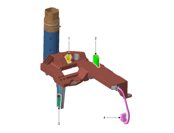
1. Drive pulley speed sensor
2. Turbine speed sensor
3. Oil temperature sensor
4. Pressure sensor connector
Drive Pulley Speed Sensor
• Drive pulley sensor is integrated into the E module.
• The sensor detects the rotation speed of the drive pulley in the Intelligent Variable Transmission (IVT) and transmits it to TCM
Turbine Speed Sensor
• Turbine speed sensor is integrated into the E module.
• Turbine speed sensor detects the speed of the turbine in the IVT and transmits it to TCM.
Oil Temperature Sensor
• Oil temperature sensor is integrated into the E module.
• Oil temperature sensor detects the Intelligent Variable Transmission Fluid (IVTF) temperature and transmits it to TCM.

• Replace the Intelligent Variable Transmission (IVT) assembly as a whole when replacement of inner parts of the IVT is required, Otherwise, dust or foreign substance may get into the IVT during disassembly, which may adversly affect its quality.
1.Replace the IVT assembly.(Refer to Intelligent Variable Transmission (IVT) System - "Intelligent Variable Transmission (IVT)")
Driven Pulley Pressure Sensor
| Item | Specification |
| Pressure (Mpa) | 0 - 6 |
| Temp [(ËšC)ËšF] | (-40 to 140) -40 to 284 |
| Output voltage (V) | 5 |
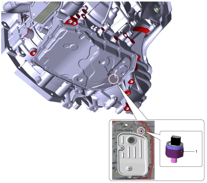
1. Driven pulley pressure sensor

• Maintain clean condition so that foreign substance does not get into the Intelligent Variable Transmission (IVT).
• Use a coated apron, latex gloves, and stainless tray to prevent foreign substance.
• Intelligent Variable Transmission (IVT) is composed of delicate components. Be careful not to cause any damage on the component when assembling and disassembling.
1.Disconnect the negative (-) battery cable.
2.Remove the engine room under cover.(Refer to Engine Mechanical System - "Engine Room Under Cover")
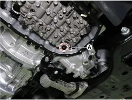
3.Remove the IVTF drain plug (A), allow the fluid to drain out and then reinstall the drain plug.
Tightening torque :34.3 - 39.2 N.m (3.5 - 4.0 kgf.m, 25.3 - 28.9 lb-ft)


• Do not reuse Intelligent Variable Transmission Fluid(IVTF).
• The existing IVTF drain plug gasket must be replaced with a new one (do not reuse).
4.Remove the valve body cover (A) after removing the bolts.
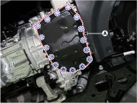

• Be careful when removing the valve body cover because the remaining IVTF remains in the valve body cover.
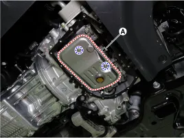
5.Remove the IVTF filter (A) after removing the bolts.

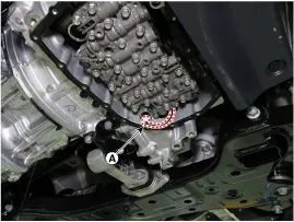
6.Disconnect the driven pulley pressure sensor connector (A).

7.Remove the driven pulley pressure sensor (A).

• Maintain clean condition so that foreign substance does not get into the Intelligent Variable Transmission (IVT).
• Use a coated apron, latex gloves, and stainless tray to prevent foreign substance.
• Intelligent Variable Transmission (IVT) is composed of delicate components. Be careful not to cause any damage on the component when assembling and disassembling.
1.Install the driven pulley pressure sensor (A).
Tightening torque :11.8 - 13.7 N.m (1.2 - 1.4 kgf.m, 8.7 - 10.1 lb-ft)

2.Connect the driven pulley pressure sensor connector (A).
3.Install the IVTF filter (A).
Tightening torque :9.8 - 11.8 N.m (1.0 - 1.2 kgf.m, 7.2 - 8.7 lb-ft)
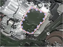
4.Install the oil pan (A).
Tightening torque :9.8 - 11.8 N.m (1.0 - 1.2 kgf.m, 7.2 - 8.7 lb-ft)

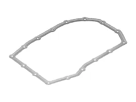
• The existing valve body cover gasket must be replaced with a new one (do not reuse).
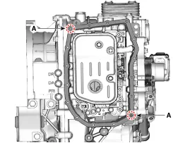
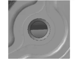
• Visually check the reference hole (A) to align the valve body cover hole with the gasket hole.
| Hole match: Assembly possible | Hole inconsistency: Oil leakage when assembled |
|
|
5.Check the IVTF level after refilling the intelligent variable transmission with fluid.(Refer to Hydraulic System - "Fluid")
6.Check for leakage of IVT fluid from engine start.
7.Install the engine room under cover.(Refer to Engine Mechanical System - "Engine Room Under Cover")
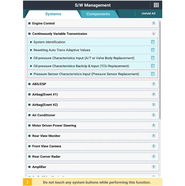
8.Perform the pressure sensor characteristics input using the diagnostic tool. (When replacing the pressure sensor)

• Input '76' in the characteristic value input field.
9.In order to avoid any problem including sense of starting delay of the transmission and shock at acceleration and vehicle start, make sure to process learning.(Refer to IVT Control System - "Adjustment")
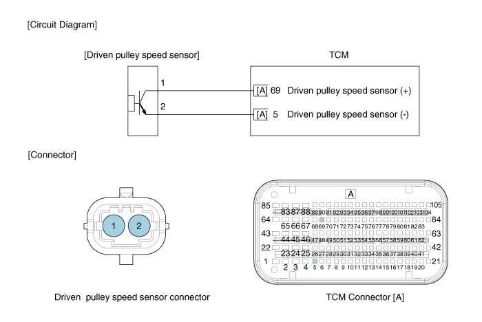
Driven Pulley Speed Sensor
| Item | Specification |
| Type | Hall sensor |
| Output voltage (V) | High : 1.18 - 1.68 (Nor : 1.4) |
| Low : 0.59 - 0.84 (Nor : 0.7) |
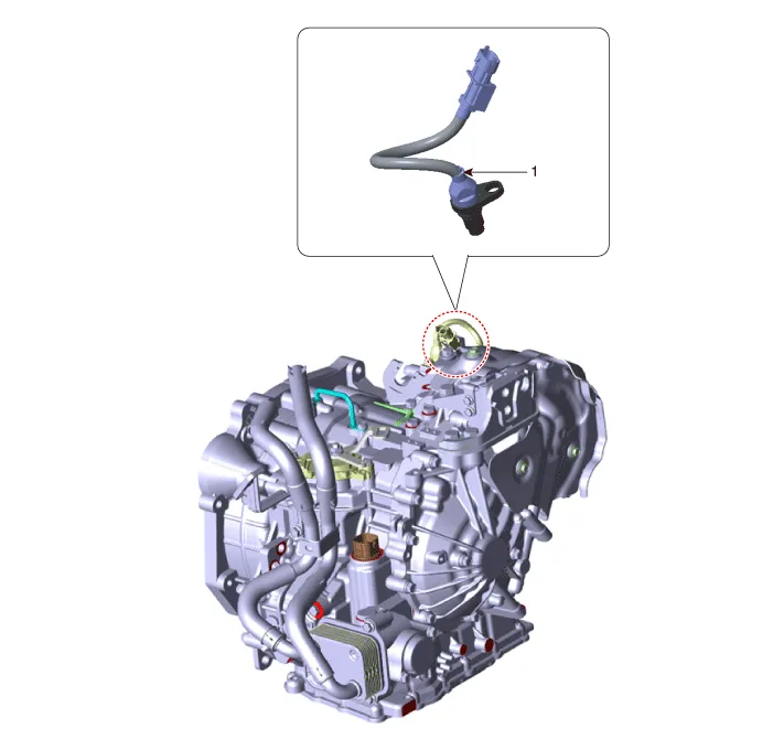
1. Driven pulley speed sensor
1.Check the sensor waveform with diagnostic tool.
1.Remove the air cleaner assembly.(Refer to Engine Mechanical System - "Air Cleaner")
2.Remove the battery and battery tray. (Refer to Body Electrical System - "Battery")
3.Disconnect the driven pulley speed sensor connector (A).
4.Remove the driven pulley speed sensor (A) after loosening the bolt.
Tightening torque:9.8 - 14.7 N.m (1.0 - 1.5 kgf.m, 7.2 - 10.8 lb-ft)
1.To install, reverse the removal procedures.
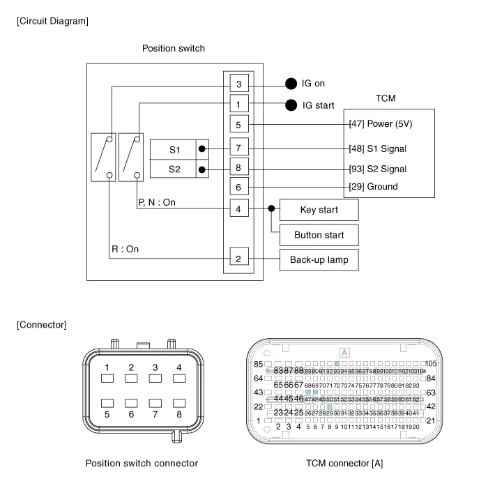
Position Switch
| Item | Specification |
| Power supply (V) | 4.5 - 5.5V |
| Output type | PWM (S1, S2), ON/OFF (Ps, Ns) |
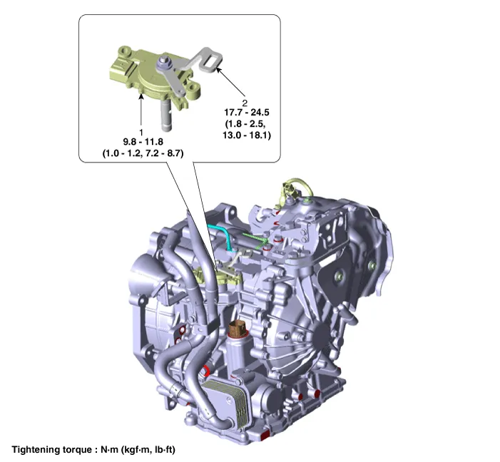
1. Position switch
2. Manual control lever

• Inspect the connector thoroughly for looseness, poor connection, bending, corrosion, contamination, deformation, or damage.
1.Disconnect the parking switch connector.
2.Turn Ignition "ON", & engine "OFF".
3.Measure the output signal in each range (P, R, N, D).
| Signal | P | R | N | D |
| S1 | 18.30% | 47.50% | 64.60% | 81.70% |
| S2 | 81.70% | 52.50% | 35.40% | 18.30% |
| Pin | Connection information |
| 1 | Power (Ps,Ns) |
| 2 | Back-up lamp |
| 3 | Power (Back-up lamp) |
| 4 | Ps ,Ns |
| 5 | Power (5V) |
| 6 | Ground (5V) |
| 7 | S1 |
| 8 | S2 |
1.Shift the gear to "N".
2.Remove the air cleaner assembly.(Refer to Engine Mechanical System - "Air Cleaner")
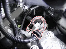
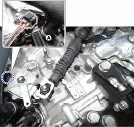
3.Disconnect the position switch connector (A) and loosen the shift cable mounting nut (B).

4.Remove the manual control lever (A) and the washer after removing a nut.
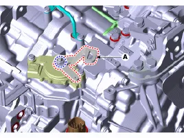
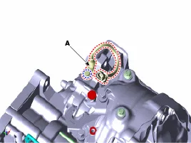
5.Remove the position switch (A) after removing the bolts.

1.Check that the gear is shifted to "N".
2.Lightly tighten the bolts after installing the position switch (A).
3.Lightly tighten the nut after installing the manual control lever (A).

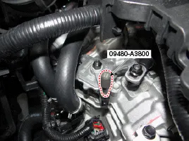
4.Align the hole in the manual control lever with the "N" position hole of the position switch and then insert the SST position switch guide pin (09480 - A3800).
5.Tighten the manual control lever nut (A) with specified toque.
Tightening torque :17.7 - 24.5 N.m (1.8 - 2.5 kgf.m, 13.0 - 18.1 lb-ft)
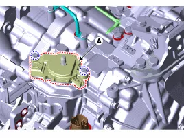
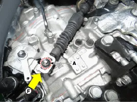
6.Tighten the position switch bolts (A) with specified toque.
Tightening torque :9.8 - 11.8 N.m (1.0 - 1.2 kgf.m, 7.2 - 8.7 lb-ft)
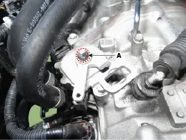
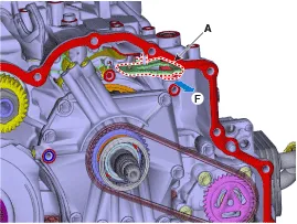
7.Push nut (A) lightly to "F" direction shown to eliminate free play of shift cable.
8.Tighten the nut (A) with the specified torque.
Tightening torque :9.8 - 14.7 N.m (1.0 - 1.5 kgf.m, 7.2 - 10.8 lb-ft)
9.Remove the SST (09480-A3800) from the adjusment hole.

10.Connect the position switch connector (A).
11.Install the air cleaner assembly.(Refer to Engine Mechanical System - "Air cleaner")
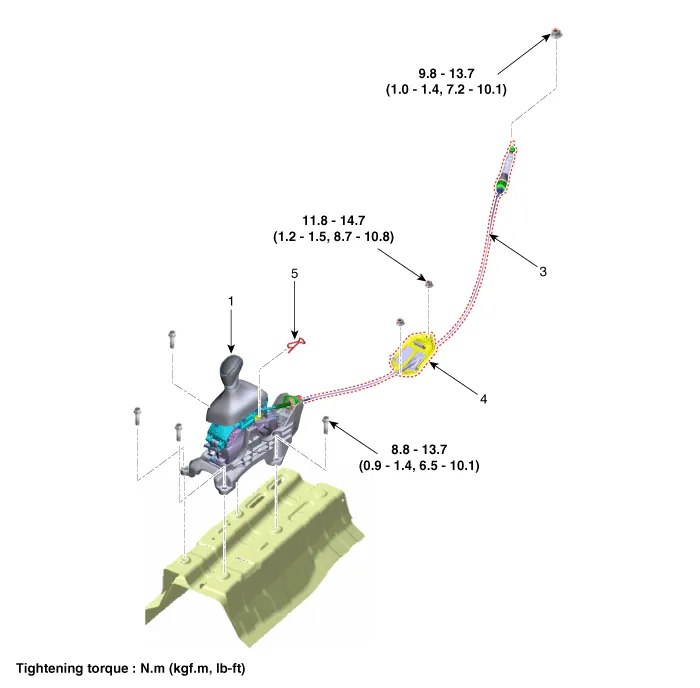
Shift Lever
1. Shift lever knob & boots
2. Shift lever assembly
3. Shift cable
4. Shift cable retainer
5. Snap pin
1.Turn ignition switch OFF and disconnect the negative (-) battery cable.
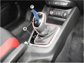
2.Pull the knob & boots (A) in the direction of "F" and remove the knob & boots (A).
3.Remove the floor console.(Refer to Body - "Floor Console")
4.Disconnect the fixing clip (A) of wiring and connector (B) from the shift lever.
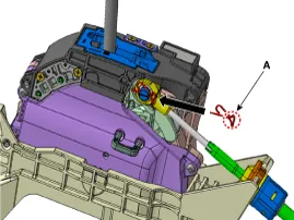
5.Disconnect the shift cable.
(1)Remove the snap pin (A).
(2)Disconnect the cable eye end (B) from the shift lever.
(3)Disconnect the cable socket (C) from the shift lever.

• Lug (A) must assemble upward.

• Bending area (A) must assemble the front.
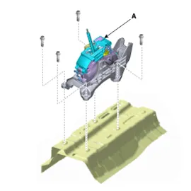
6.Remove the bolts and then shift lever assembly (A).
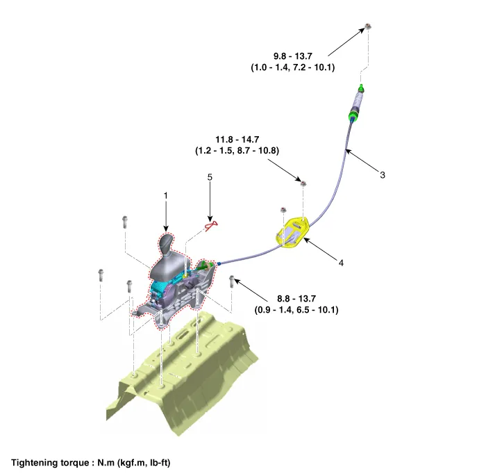
Tightening torque :8.8 - 13.7 N.m (0.9 - 1.4 kgf.m, 6.5 - 10.1 lb-ft)
1.To install, reverse the removal procedure.

• Install the cable after placing the shift lever and the manual control lever in the N position.
Shift Cable
1. Shift lever knob & boots
2. Shift lever assembly
3. Shift cable
4. shift cable retainer
5. Snap pin
1.Remove the air cleaner assembly and air duct.(Refer to Engine Mechanical System - "Air Cleaner")
2.Remove the battery and battery tray.(Refer to Engine Electrical System - "Battery")
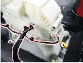
3.Remove the nut (A) from the manual control lever.
4.Remove the shift cable (B) from the bracket (C) at transaxle side.
5.Remove the floor console assembly. (Refer to Body - "Floor Console")
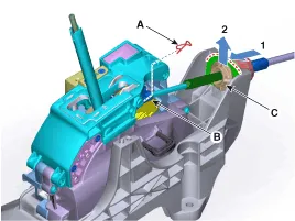
6.Disconnect the shift cable.
(1)Remove the snap pin (A).
(2)Disconnect the cable eye end (B) from the shift lever.
(3)Disconnect the cable socket (C) from the shift lever.

7.Disconnect the shift cable retainer after removing the nuts (A).
8.Remove the shift cable by pulling it toward the interior.
1.Install the shift cable retainer (A).
Tightening torque : 11.8 - 14.7 N.m (1.2 - 1.5 kgf.m, 8.7 - 10.8 lb-ft)

• Install the cable after placing the shift lever and the manual control lever in the N position.
2.Install the shift cable (A) in the shifter lever.

• Lug (A) must assemble upward.
• When assembling the snap pin, be careful about the correct direction. - The band portion (A) must point to the front of the vehicle. - The band portion (A) must point outwards.

3.Install the shift cable (B) in the cable bracket (C).
4.Align the hole (E) in the manual control lever with the "N" position hole (G) of the inhibitor switch and then insert the inhibitor switch guide pin (SST No: 09480-A3800).
5.Lightly tighten the nut (A) after connected the shift cable (B) in the manual control lever (D).
6.Push the shift cable (B) lightly to "F" direction shown to eliminate free play of shift cable.
7.Tighten the nut (A) to the specified torque.
Tightening torque : 9.8 - 13.7 N.m (1.0 - 1.4 kgf.m, 7.2 - 10.1 lb-ft)
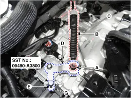
8.Remove the inhibitor switch guide pin (SST No.: 09480-A3800) from the hole.
9.Install the floor console assembly.(Refer to Body - "Floor Console")
10.Install the air cleaner assembly.(Refer to Engine Mechanical System - "Air Cleaner")
11.Install the battery and battery tray.(Refer to Engine Electrical System - "Battery")
12.Install the air duct.(Refer to Engine Mechanical System - "Air Cleaner")
13.Check that operating surely at each range of the position switch corresponding to each position of shift lever.
Parking Sprag
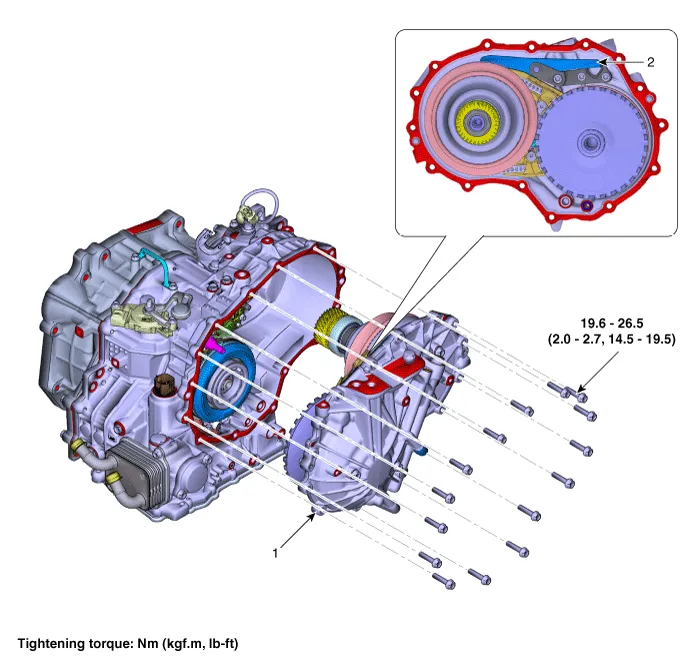
1. Rear housing
2. Parking sprag
1.Set shift lever to N position.
2.Remove the IVTF drain plug allow the fluid to drain out and then reinstall the drain plug.(Refer to Hydraulic System - "Fluid")
3.Remove the Intelligent Variable Transmission (IVT).(Refer to Intelligent Variable Transmission (IVT) System (C0GF1) - "Intelligent Variable Transmission (IVT)")
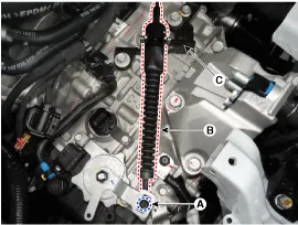
4.Loosen the bolts and then removing the heat protector (A, B, C).
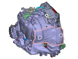
5.Loosen the bolts and then removing the rear housing (A).
Tightening torque : 19.6 - 26.5 N.m (2.0 - 2.7 kgf.m, 14.5 - 19.5 lb-ft)
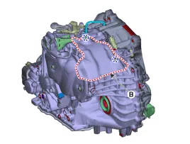
6.Loosen the bolts and then removing the parking sprag (A) from rear housing.
Tightening torque : 24.5 - 29.4 N.m (2.5 - 3.0 kgf.m, 18.1 - 21.7 lb-ft)

• Before mounting, replace the parking rod cam if there are excessive flaws on the outside of the parking rod cam (A).(Refer to IVT Control System - "Parking Rod Cam")
• Make sure that there is an O-ring on the side of the case.
• Remove the old sealant from the mounting surface and apply a new sealant.
1.To install reverse the removal procedures.
2.Injection the IVT fluid.(Refer to Hydraulic System - "Fluid")
Parking Rod Cam
1.Remove the IVTF drain plug allow the fluid to drain out and then reinstall the drain plug.(Refer to Hydraulic System - "Fluid")
2.Remove the Intelligent Variable Transmission (IVT).(Refer to Intelligent Variable Transmission (IVT) System (C0GF1) - "Intelligent Variable Transmission (IVT)")
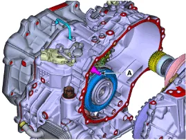
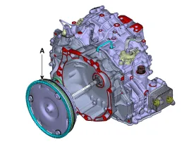
3.Remove the torque convertor (A) from convertor housing.
4.Loosen the bolts and nut and then removing the position switch (A).
Tightening torque : Manual lever mounting nut : 17.7 - 24.5 N.m (1.8 - 2.5 kgf.m, 13.0 - 18.1 lb-ft) Position switch mounting bolt : 9.8 - 11.8 N.m (1.0 - 1.2 kgf.m, 7.2 - 8.7 lb-ft)
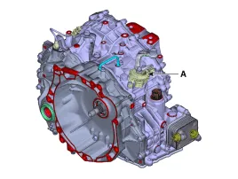
5.Loosen the bolts and then removing the tube (A).
Tightening torque : 9.8 - 11.8 N.m (1.0 - 1.2 kgf.m, 7.2 - 8.7 lb-ft)
6.Loosen the bolts and then removing the torque convertor (A).
Tightening torque : 27.5 - 34.3 N.m (2.8 - 3.5 kgf.m, 20.1 - 25.3 lb-ft)
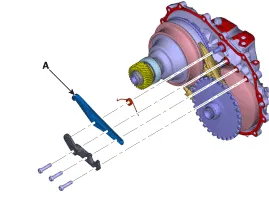
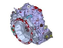
7.Loosen the bolt and then removing the manual guide (A).
8.Loosen the bolts (A) and then removing the manual shaft (B).
Tightening torque : 9.8 - 11.8 N.m (1.0 - 1.2 kgf.m, 7.2 - 8.7 lb-ft)
9.Remove the parking rod assembly (A) in the "F" direction.
10.Remove the parking rod cam (A) from parking rod assembly.

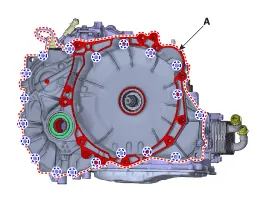
• Remove the old sealant from the mounting surface and apply a new sealant.
1.To install reverse the removal procedures.
2.Injection the IVT fluid.(Refer to Hydraulic System - "Fluid")


Other information:
Hyundai Accent (HC) (2017 - 2022) Service Manual: Troubleshooting
- Basic Troubleshooting Basic Troubleshooting Guide Customer Problem Analysis Sheet Basic Inspection Procedure Measuring Condition Of Electronic Parts' Resistance The measured resistance at high temperature after vehicle running may be high or low. So all resistance must be measured at ambient temperature (20°C, 68°F), unless stated otherwise.Hyundai Accent (HC) (2017 - 2022) Service Manual: Repair procedures
- Diagnosis with Diagnostic tool 1.In the body electrical system, failure can be quickly diagnosed by using the vehicle diagnostic system (Diagnostic tool).The diagnostic system (Diagnostic tool) provides the following information.(1)Fault Code Searching : Checking failure and code number (DTC) (2)Data Analysis : Checking the system input/output data state (3)Actuation test : Checking the system operation condition (4)S/W Management : Controlling other features including system option setting and zero point adjustment Data Analysis 1.
Contents
- Description and Operation
- Repair procedures
- Transmission Control Module (TCM)
- E-Module
- Driven Pulley Pressure Sensor
- Driven Pulley Speed Sensor
- Position Switch
- Shift Lever
- Shift Cable
- Parking Sprag
- Parking Rod Cam
Categories
- Manuals Home
- Hyundai Accent Owners Manual
- Hyundai Accent Service Manual
- Questions & Answers
- Video Guides
- Useful Resources
- New on site
- Most important about car
- Privacy Policy

0.0092