Hyundai Accent (HC): Heater / Auto Defoging Actuator
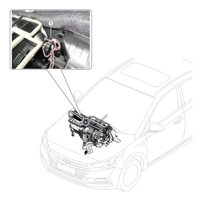
1. Auto logging actuator
1.Turn the ignition switch OFF.
2.Disconnect the auto defogging connector.
3.Verify that the auto defogging actuator operates to the open position when connecting 12V to terminal 3 and grounding terminal 4. Verify that the auto defogging actuator operates to the close position when connected in reverse.
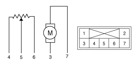
1. -
2. -
3. DEF (Open)
4. Sensor (+ 5V)
5. Feedback signal
6. Sensoer ground
7. DEF (Close)
4.Connect the auto defogging actuator connector.
5.Turn the ignition switch ON.
6.Check the voltage between terminals 6 and 5.

• It will feedback the current position of the actuator to controls.
Specification| Door position | Voltage (V) | Error detecting |
| Vent | 4.7 ± 0.15 | High voltage : 2.06V or more |
| Defrost | 2.06 ± 0.15 | Low voltage : 2.06V or less |
7.If the measured voltage is not within specification, check the operation by replacing the existing auto defogging actuator with a new genuine part. After that, determine whether replacement of the auto defogging actuator is required or not.
1.The heating, ventilation and air conditioning can be quickly diagnosed failed parts with vehicle diagnostic system (GDS).※ The diagnostic system (GDS) provides the following information.(1) Self diagnosis : Checking the failure code (DTC) and display.(2) Current data : Checking the system input/output data state.(3) Actuation test : Checking the system operation condition.(4) Additional function : Other controlling such as he system option and zero point adjustment.
2.Select the 'Car model' and the system to be checked in order to check the vehicle with the tester.
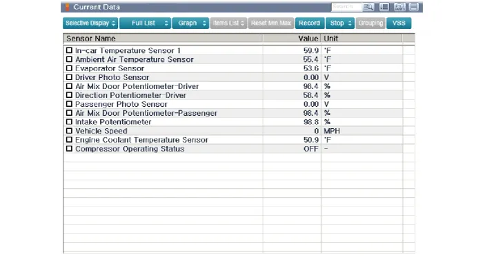
3.Select the 'Current data' menu to search the current state of the input / output data.The input / output data for the sensors corresponding to the Auto Defogging Actuator can be checked.
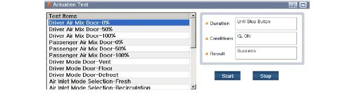
4.To perform compulsory operation on Auto Defogging Actuator input factors, select "ACTUATION TEST".
1.Disconnect the negative (-) battery terminal.
2.Remove the main crash pad assembly.(Refer to Body - "Main Crash Pad Assembly")
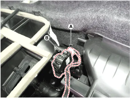
3.Disconnect the connector (A) and then remove the auto defogging actuator (B) after loosening the mounting screws.
4.To install, reverse the removal procedure.


Other information:
Hyundai Accent (HC) (2017 - 2022) Service Manual: Front Stabilizer Bar
- Removal 1.Loosen the wheel nuts slightly.Raise the vehicle, and make sure it is securely supported. 2.Remove the front wheel and tire (A) from the front hub.Tightening torque :107.9 - 127.5 N.m (11.0 - 13.0 kgf.m, 79.6 - 94.0 lb-ft) • Be careful not to damage the hub bolts when removing the front wheel and tire. 3.Hyundai Accent (HC) (2017 - 2022) Service Manual: Rear Drum Brake
- Components 1. Shoe hold down pin 2. Shoe adjuster 3. Upper return spring4. Adjusting lever5. Shoe6. Adjusting spring7. Lower return spring8. Shoe hold spring - Removal 1.Loosen the wheel nuts slightly. Raise the vehicle, and make sure it is securely supported. 2.Remove the rear wheel and tire (A).Tightening torque :107.9 - 127.5 N.
Categories
- Manuals Home
- Hyundai Accent Owners Manual
- Hyundai Accent Service Manual
- Questions & Answers
- Video Guides
- Useful Resources
- New on site
- Most important about car
- Privacy Policy

0.005