Hyundai Accent (HC): Heating, Ventilation and Air Conditioning / Heater
Contents:
- Heater Unit
- Heater Core
- Evaporator Core
- Temperature Control Actuator
- Mode Control Actuator
- Auto Defoging Actuator
Heater Unit
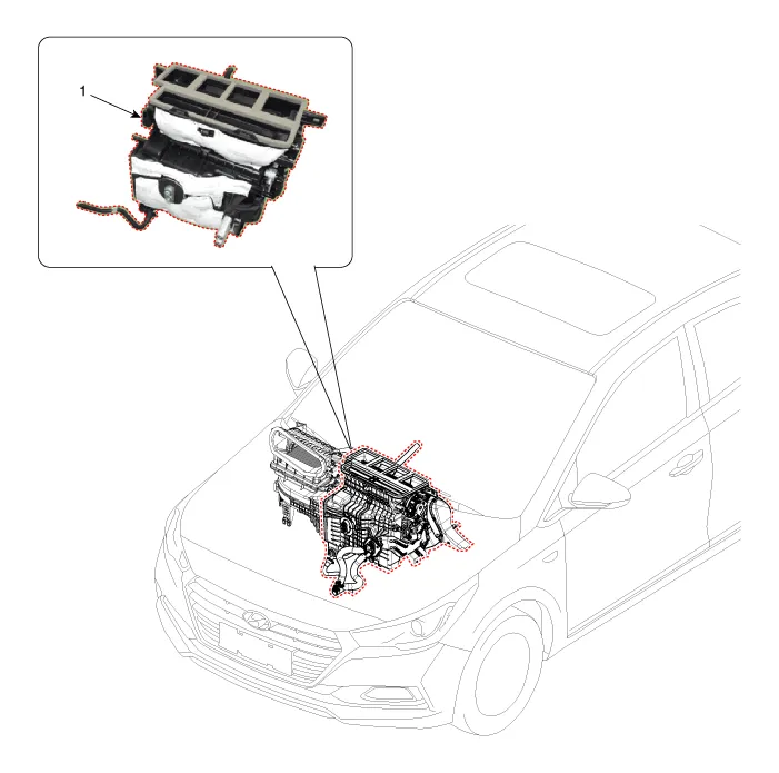
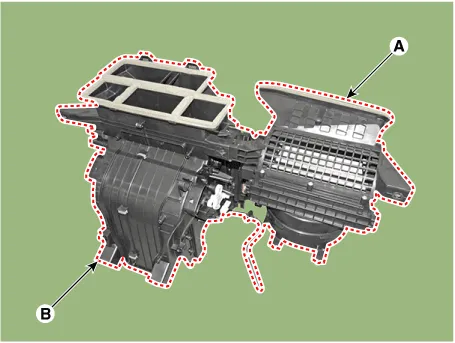
1. Heater unit assembly
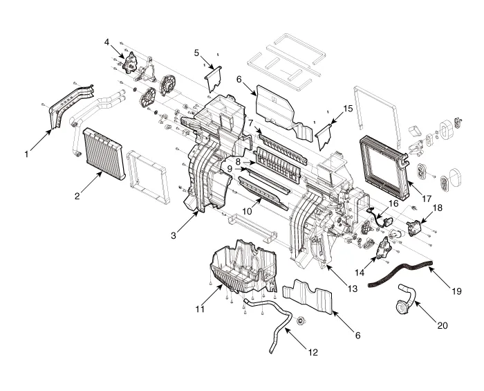
1. Heater core cover
2. Heater core & seal assembly
3. Heater case [LH]
4. Mode control actuator
5. Air guide [LH]
6. Heater unit pad
7. Deforster door assembly
8. Vent door assembly
9. Floor door assembly
10. Temperature door assembly
11. Lower case
12. Drain hose
13. Heater case [RH]
14. Temperature control actuator
15. Air guide [RH]
16. Evaporator temperature sensor
17. Evaporator core
18. Auto defogging actuator
19. Inhale hose
20. Cool box assembly

1.Disconnect the negative (-) battery terminal.
2.Recover the refrigerant with a recovery / recycling / charging station.
3.When the engine is cool, drain the engine coolant from the radiator.(Refer to Engine Mechanical System - "Coolant")
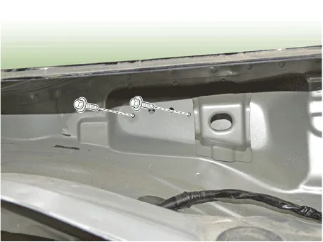
4.Remove the cowl top cover.(Refer to Body - "Cowl Top Cover")
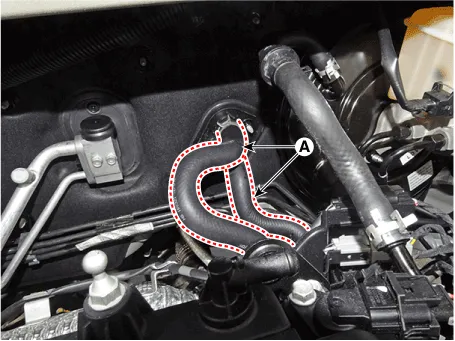
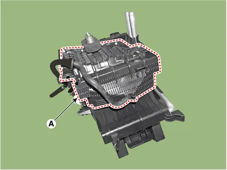
5.Remove the bolts and the expansion valve (A) from the evaporator core.
Tightening torque : 8.8 - 13.7 N.m (0.9 - 1.4 kgf.m, 6.5 - 10.1 Ib-ft)

• Plug or cap the lines immediately after disconnecting them to avoid moisture and dust contamination.
• When installing, replace with a new O-ring.
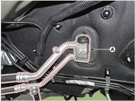
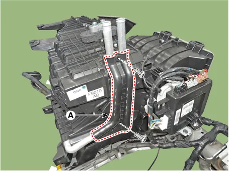
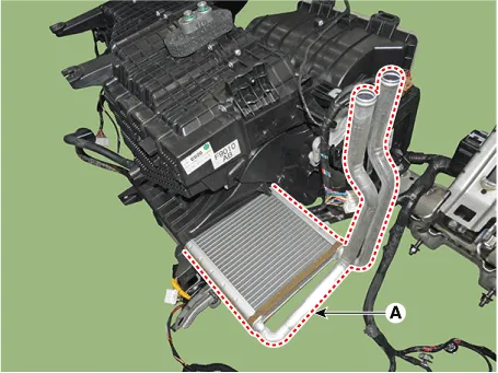
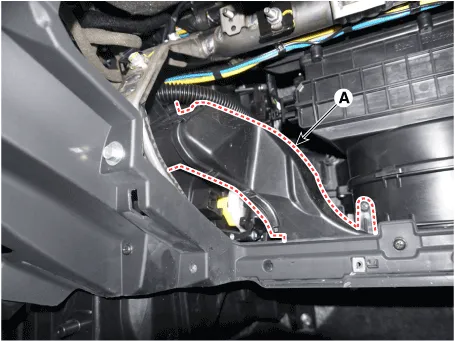
6.Disconnect the heater hoses (A) from the heater unit.

• Engine coolant will run out when the hoses are disconnected; drain it into a clean drip pan. Be sure not to let coolant spill on electrical parts or painted surfaces. If any coolant spills, rinse it off immediately.
7.Loosen the cowl cross member mounting bolts.
Tightening torque : 16.7 - 25.5 N.m (1.7 - 2.6 kgf.m, 12.3 -18.8 lb-ft)
8.Remove the floor console assembly.(Refer to Body - "Floor Console Assembly")
9.Remove the crash pad lower panel.(Refer to Body - "Crash Pad Lower Panel")
10.Remove both sides of the front pillar trim.(Refer to Body - "Front Pillar Trim")
11.Remove the cowl side trim.(Refer to Body - "Cowl Side Trim")
12.Remove the steering column shroud lower panel.(Refer to Body - "Steering Column Shroud Panel")
13.Remove the steering wheel.(Refer to Steering System - "Steering Wheel")
14.Remove the multifunction switch.(Refer to Body Electrical System - "Multifunction Switch")
15.Lower the steering column after loosening the mounting bolts.(Refer to Steering System - "Steering Column and Shaft")
16.Remove the shift lever assembly.(Refer to Automatic Transmission System - "Shift Lever")
17.Remove the rear air duct (A).

18.Separate the floor carpet (A) to obtain space for removing the rear heating duct.
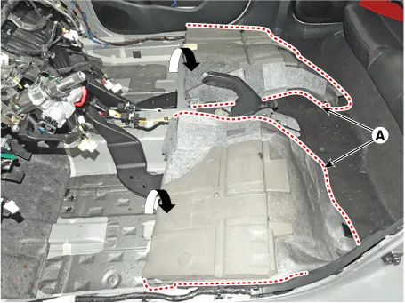
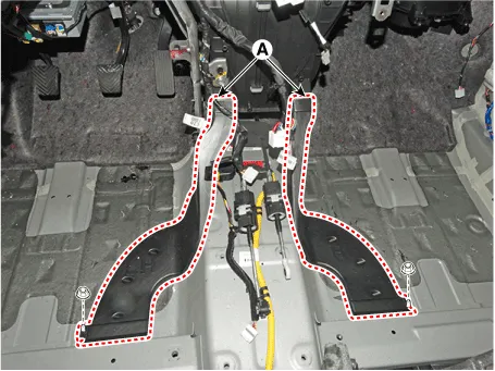
19.Loosen the mounting nuts and remove the front air duct (A).
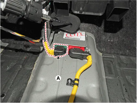
20.Disconnect the airbag control module (SRSCM) connector (A).
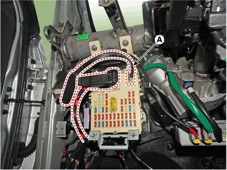
21.Disconnect the junction box connectors (A).
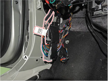
22.Disconnect the multi box connectors (A).[Driver's side]
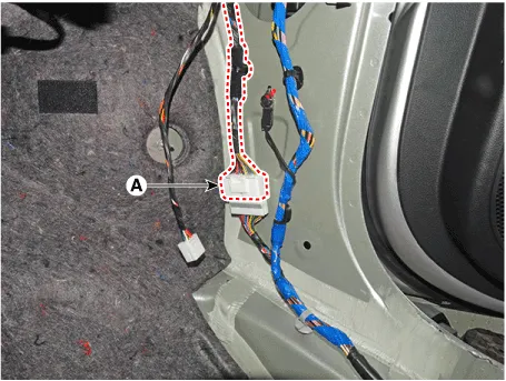
23.Disconnect the connectors (A) and the mounting clips in the front pillar.
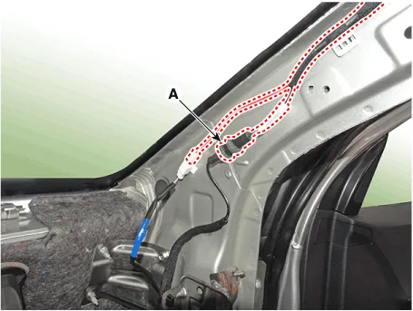
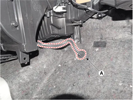
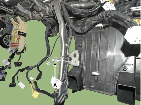
24.Remove the drain hose (A).
25.Loosen the cowl blower unit mounting bolts.
Tightening torque :3.9 - 5.9 N.m (0.4 - 0.6 kgf.m, 2.9 - 4.3 Ib-ft)
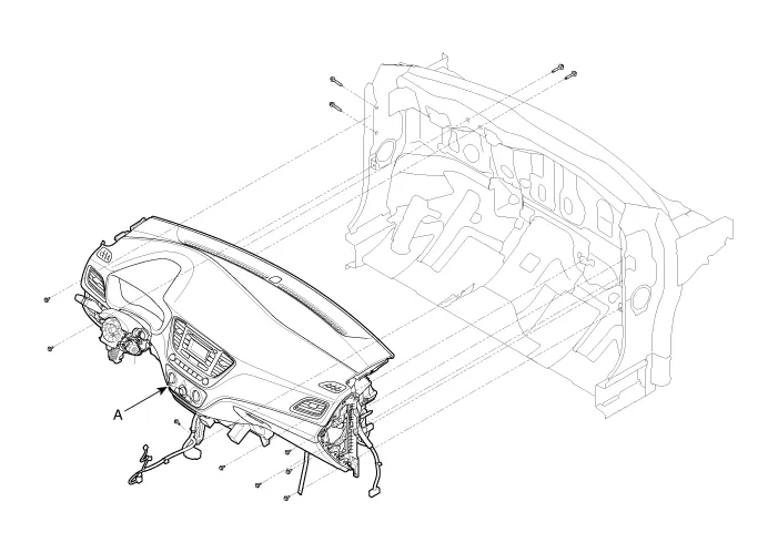
26.After loosening the bolts and nuts remove the main crash pad and cowl cross bar assembly (A) together.
27.Disconnect the heater & blower unit connectors.
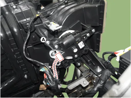
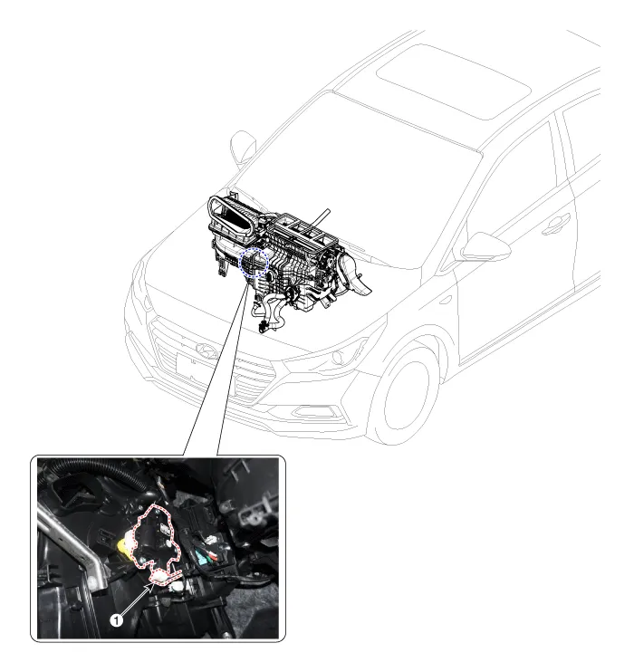
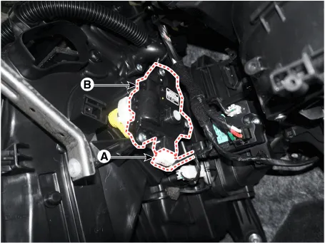
(1)Disconnect the mode actuator connector (A) and remove the wiring mounting clips.
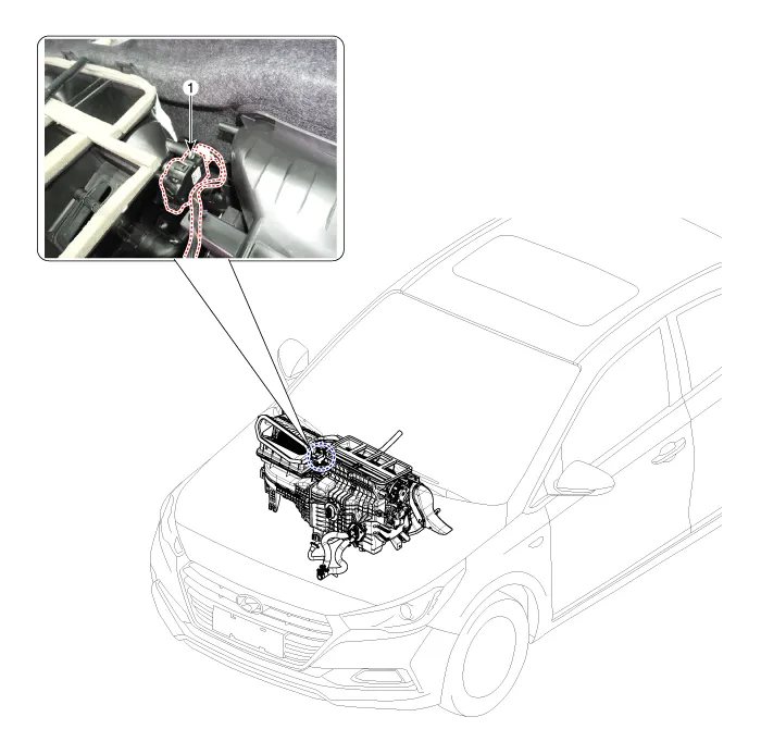
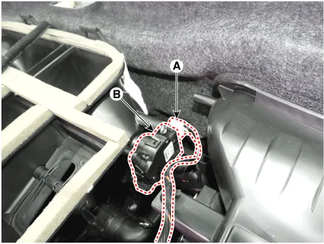
(2)Disconnect the auto defogging actuator connector (A) and intake actuator connector (B) remove the wiring mounting clips.
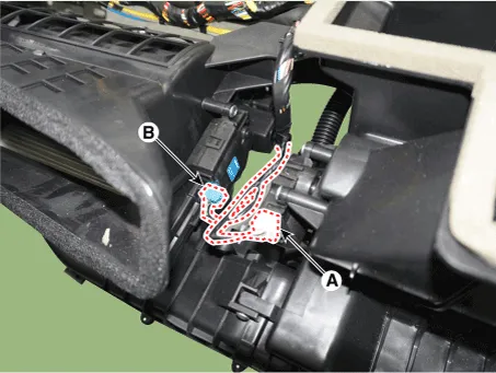
(3)Disconnect the temperature control actuator (A), power mosfet connector (B) and remove the wiring mounting clips.
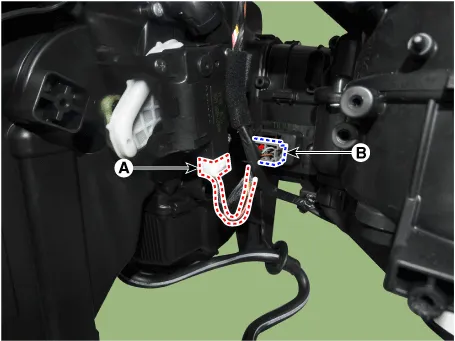
(4)Disconnect the blower motor connector (A) and remove the wiring mounting clips.
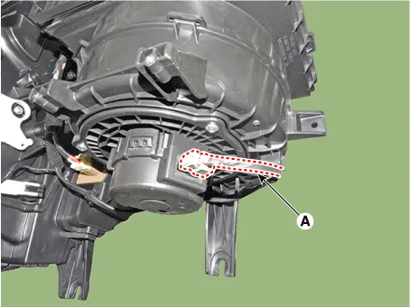
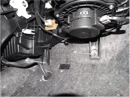
28.Loosen the heater & blower unit mounting bolt (A).
29.Remove the heater and blower unit from the crash pad after loosening the mounting nuts.
30.Separate the blower unit (A) from the heater unit (B) after loosening the screws.
31.To install, reverse the removal procedure.
Heater Core
1.Disconnect the negative (-) battery terminal.
2.Remove the heater and blower unit from the crash pad after loosening the mounting nuts.(Refer to Heater - "Heater Unit")
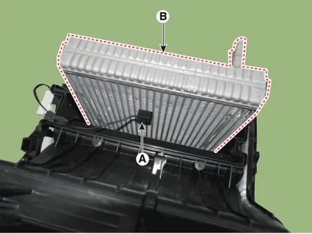
3.Remove the heater core cover (A) after loosening the mounting screws.
4.Pull out the heater core (A) from the heater unit.
5.To install, reverse the removal procedure.

• If you're installing a new heater core, add refrigerant oil (PAG OIL).
• Replace the O-rings with new ones at each fitting, and apply a thin coat of refrigerant oil before installing them. Be sure to use the right O-rings for R-1234yf to avoid leakage.
• Immediately after using the oil, replace the cap on the container, and seal it to avoid moisture absorption.
• Do not spill the refrigerant oil on the vehicle ; it may damage the paint, if the refrigerant oil contacts the paint, wash it off immediately.
• Apply sealant to the grommets.
• Make sure that there is no air leakage.
• Charge the system and test its performance.
• Do not interchange the inlet and outlet heater hoses and install the hose clamps securely.
Evaporator Core
1.Disconnect the negative (-) battery terminal.
2.Remove the heater and blower unit from the crash pad after loosening the mounting nuts.(Refer to Heater - "Heater Unit")
3.Remove the evaporator core cover (A) after loosening the mounting screws.
4.Pull out the evaporator core (A) from the heater unit.
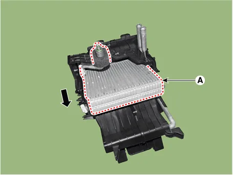
5.Remove the evaporator temperature sensor (A) from the evaporator core (B).
6.To install, reverse the removal procedure.

• If you're installing a new heater core, add refrigerant oil (PAG OIL).
• Replace the O-rings with new ones at each fitting, and apply a thin coat of refrigerant oil before installing them. Be sure to use the right O-rings for R-1234yf to avoid leakage.
• Immediately after using the oil, replace the cap on the container, and seal it to avoid moisture absorption.
• Do not spill the refrigerant oil on the vehicle ; it may damage the paint, if the refrigerant oil contacts the paint, wash it off immediately.
• Apply sealant to the grommets.
• Make sure that there is no air leakage.
• Charge the system and test its performance.
• Do not interchange the inlet and outlet heater hoses and install the hose clamps securely.
Temperature Control Actuator
1. Temperature control actuator
| Door Position | Voltage (V) | Error Detecting |
| Max. cooling | 0.3 ± 0.15 | Low voltage : 0.1V or less High voltage : 4.9V or more |
| Max. heating | 4.7 ± 0.15 |
1.Turn the ignition switch OFF.
2.Disconnect the temperature control actuator connector.
3.Verify that the temperature control actuator operates to the cool position when connecting 12V to terminal 6 and grounding terminal 5.Verify that the temperature control actuator operates to the warm position when connected in reverse.

| Pin NO | Function |
| 1 | - |
| 2 | - |
| 3 | Warm position |
| 4 | Sensor ground |
| 5 | Feedback signal |
| 6 | Sensor (+5V) |
| 7 | Cool position |
4.Connect the temperature control actuator connector.
5.Turn the ignition switch ON.
6.Check the voltage between terminal 5 and 6.
7.If the measured voltage is not within specification, check the operation by replacing the existing temperature control actuator with a new genuine part. After that, determine whether replacement of the temperature control actuator is required or not.
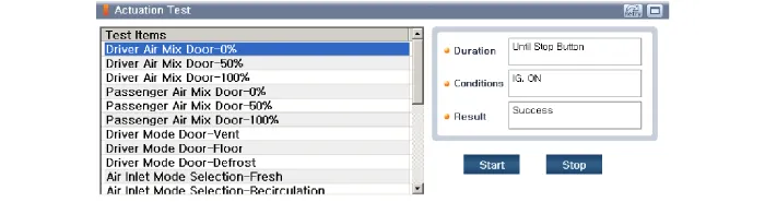
1.The heating, ventilation and air conditioning can be quickly diagnosed failed parts with vehicle diagnostic system (GDS).※ The diagnostic system (GDS) provides the following information.(1) Self diagnosis : Checking the failure code (DTC) and display.(2) Current data : Checking the system input / output data state.(3) Actuation test : Checking the system operation condition.(4) Additional function : Other controlling such as he system option and zero point adjustment.
2.Select the 'Car model' and the system to be checked in order to check the vehicle with the tester.
3.Select the 'Current data' menu to search the current state of the input / output data.The input / output data for the sensors corresponding to the Temperature Control Actuator can be checked.
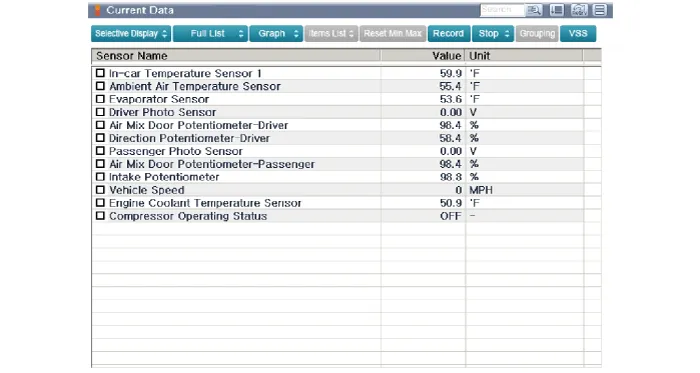
4.To perform compulsory operation on Temperature Control Actuator input factors, select "ACTUATION TEST".

1.Disconnect the negative (-) battery terminal.
2.Remove the glove box upper cover housing assembly.(Refer to Body - "Glove Box Upper Cover Housing Assembly")
3.Remove the passenger's side shower duct (A) after loosening the screw.
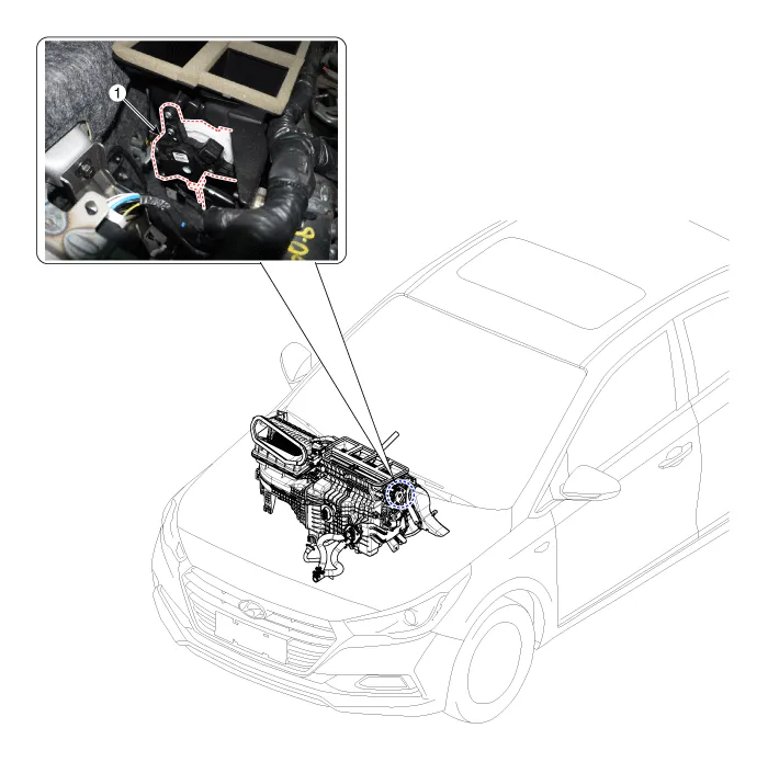
4.Disconnect the connector (A) and then remove the temperature control actuator (B) after loosening the mounting screws.
5.To install, reverse the removal procedure.
Mode Control Actuator
1. Mode control actuator
| Door position | Voltage (V) | Error detecting |
| Vent | 0.3 ± 0.15 | Low voltage : 0.1V or less |
| Defrost | 4.7 ± 0.15 | High voltage : 4.9V or more |
1.Turn the ignition switch OFF.
2.Disconnect the mode control actuator connector.
3.Verify that the mode control actuator operates to the defrost mode when connecting 12V to terminal 6 and grounding terminal 5.Verify that the mode control actuator operates to the vent mode when connected in reverse.

| Pin NO | Function |
| 1 | - |
| 2 | - |
| 3 | Defrost mode |
| 4 | Sensor ground |
| 5 | Feedback signal |
| 6 | Sensor (+5V) |
| 7 | Vent mode |
4.Connect the mode control actuator connector.
5.Turn the ignition switch ON.
6.Check the voltage between terminal 6 and 5.
7.If the measured voltage is not within specification, check the operation by replacing the existing mode control actuator with a new genuine part. After that, determine whether replacement of the temperature control actuator is required or not.
1.The heating, ventilation and air conditioning can be quickly diagnosed failed parts with vehicle diagnostic system (GDS).※ The diagnostic system (GDS) provides the following information.(1) Self diagnosis : Checking the failure code (DTC) and display.(2) Current data : Checking the system input / output data state.(3) Actuation test : Checking the system operation condition.(4) Additional function : Other controlling such as he system option and zero point adjustment.
2.Select the 'Car model' and the system to be checked in order to check the vehicle with the tester.
3.Select the 'Current data' menu to search the current state of the input / output data.The input / output data for the sensors corresponding to the Mode Control Actuator can be checked.

4.To perform compulsory operation on Mode Control Actuator input factors, select "ACTUATION TEST".
1.Disconnect the negative (-) battery terminal.
2.Remove the main crash pad assembly.(Refer to Body - "Main Crash Pad Assembly")
3.Remove the BCM (Body Control Module) cluster.(Refer to Body Electrical System - "BCM (Body Control Module)")
4.Disconnect the connector (A) and then remove the mode control actuator (B) after loosening the mounting screws.

5.To install, reverse the removal procedure.
Auto Defoging Actuator
1. Auto logging actuator
1.Turn the ignition switch OFF.
2.Disconnect the auto defogging connector.
3.Verify that the auto defogging actuator operates to the open position when connecting 12V to terminal 3 and grounding terminal 4. Verify that the auto defogging actuator operates to the close position when connected in reverse.

1. -
2. -
3. DEF (Open)
4. Sensor (+ 5V)
5. Feedback signal
6. Sensoer ground
7. DEF (Close)
4.Connect the auto defogging actuator connector.
5.Turn the ignition switch ON.
6.Check the voltage between terminals 6 and 5.

• It will feedback the current position of the actuator to controls.
Specification| Door position | Voltage (V) | Error detecting |
| Vent | 4.7 ± 0.15 | High voltage : 2.06V or more |
| Defrost | 2.06 ± 0.15 | Low voltage : 2.06V or less |
7.If the measured voltage is not within specification, check the operation by replacing the existing auto defogging actuator with a new genuine part. After that, determine whether replacement of the auto defogging actuator is required or not.
1.The heating, ventilation and air conditioning can be quickly diagnosed failed parts with vehicle diagnostic system (GDS).※ The diagnostic system (GDS) provides the following information.(1) Self diagnosis : Checking the failure code (DTC) and display.(2) Current data : Checking the system input/output data state.(3) Actuation test : Checking the system operation condition.(4) Additional function : Other controlling such as he system option and zero point adjustment.
2.Select the 'Car model' and the system to be checked in order to check the vehicle with the tester.
3.Select the 'Current data' menu to search the current state of the input / output data.The input / output data for the sensors corresponding to the Auto Defogging Actuator can be checked.

4.To perform compulsory operation on Auto Defogging Actuator input factors, select "ACTUATION TEST".

1.Disconnect the negative (-) battery terminal.
2.Remove the main crash pad assembly.(Refer to Body - "Main Crash Pad Assembly")
3.Disconnect the connector (A) and then remove the auto defogging actuator (B) after loosening the mounting screws.
4.To install, reverse the removal procedure.


Other information:
Hyundai Accent (HC) (2017 - 2022) Service Manual: Description and Operation
- Description Burglar Alarm State [B/A State] B/A StateDescription DISARM1) In "DISARM" state, no vehicle start inhibition. So, when door, hood, or Tailgate is opened, there is no alarm sound and flashing. 2) If the battery is disconnected while the state is not "ARM/ARMWAIT/ALARM/REARM", B/A state is set to "DISARM" state. 3)In "DISARM" state, security indicator keeps blinking.
Contents
- Heater Unit
- Heater Core
- Evaporator Core
- Temperature Control Actuator
- Mode Control Actuator
- Auto Defoging Actuator
Categories
- Manuals Home
- Hyundai Accent Owners Manual
- Hyundai Accent Service Manual
- Questions & Answers
- Video Guides
- Useful Resources
- New on site
- Most important about car
- Privacy Policy

0.0067