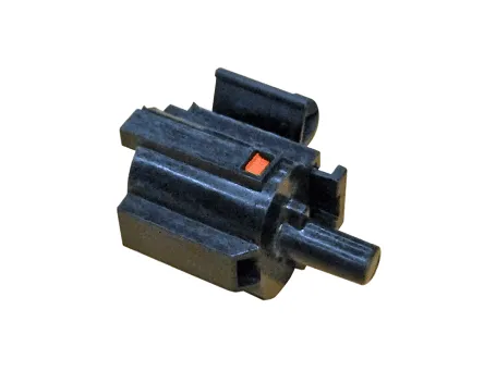
Hyundai Accent (HC): Air Conditioning System / Ambient Temperature Sensor

1.Check the resistance of the ambient temperature sensor between terminals 1 and 2 whether it changes by changing the ambient temperature.
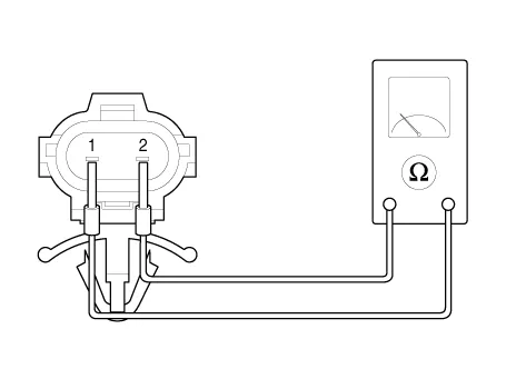
1. Ambient Sensor (+)
2. Sensor ground
| Ambient temperature [°C (°F)] | Resistance between terminal 1 and 2 (kΩ) |
| -30 (-22) | 480.41 |
| -20 (-4) | 271.21 |
| -10 (14) | 158.18 |
| 0 (32) | 95.096 |
| 10 (50) | 58.799 |
| 20 (68) | 37.315 |
| 30 (86) | 24.26 |
| 40 (104) | 16.13 |
| 50 (122) | 10.95 |
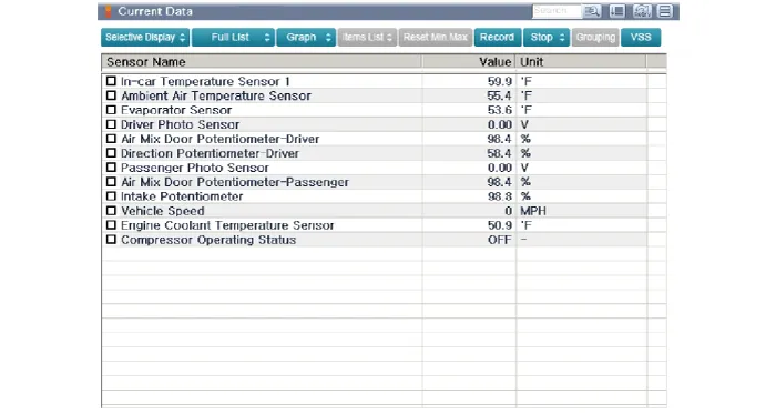
1.The heating, ventilation and air conditioning can be quickly diagnosed failed parts with vehicle diagnostic system (GDS).※ The diagnostic system (GDS) provides the following information.(1) Self diagnosis : Checking the failure code (DTC) and display.(2) Current data : Checking the system input / output data state.(3) Actuation test : Checking the system operation condition.(4) Additional function : Other controlling such as he system option and zero point adjustment.
2.Select the 'Car model' and the system to be checked in order to check the vehicle with the tester.
3.Select the 'Current data' menu to search the current state of the input / output data.The input / output data for the sensors corresponding to the Ambient Temperature Sensor can be checked.
1.Disconnect the negative (-) battery terminal.
2.Remove the engine room under cover.(Refer to Engine Mechanical System - "Engine Room Cover")
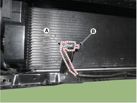
3.Disconnect the connector (A) and then remove the ambient temperature sensor (B).
4.To install, reverse the removal procedure.


Other information:
Hyundai Accent (HC) (2017 - 2022) Service Manual: Rear Disc Brake
- Components 1. Return spring2. Operating lever3. Stopper4. Guide rod pin5. Guide rod boot6. Caliper carrier7. Pad retainer8. Brake pad9. Pad return spring10.Caliper body - Removal 1.Loosen the wheel nuts slightly.Raise the vehicle, and make sure it is securely supported. 2.Remove the rear wheel and tire (A) from front hub.Tightening torque :107.Hyundai Accent (HC) (2017 - 2022) Service Manual: Control Shaft Complete
- Components 1. Control shaft complete - Removal 1.Set shift lever to N position. 2.Turn OFF ignition switch and disconnect the negative (-) battery cable. 3.Remove the air cleaner assembly and air duct.(Refer to Engine Mechanical System - "Air Cleaner") 4.Remove the battery and battery tray.(Refer to Engine Electrical System - "Battery") 5.
Categories
- Manuals Home
- Hyundai Accent Owners Manual
- Hyundai Accent Service Manual
- Questions & Answers
- Video Guides
- Useful Resources
- New on site
- Most important about car
- Privacy Policy

0.0057