Hyundai Accent (HC): Heating, Ventilation and Air Conditioning / Air Conditioning System
Contents:
- General Safety Information and Caution
- Description and Operation
- Repair procedures
- Components and Components Location
- Compressor oil
- Refrigerant Line
- Compressor
- Condenser
- Receiver-Drier
- A/C Pressure Transducer
- Evaporator Temperature Sensor
- In-car Sensor
- Photo Sensor
- Ambient Temperature Sensor
General Safety Information and Caution ➤
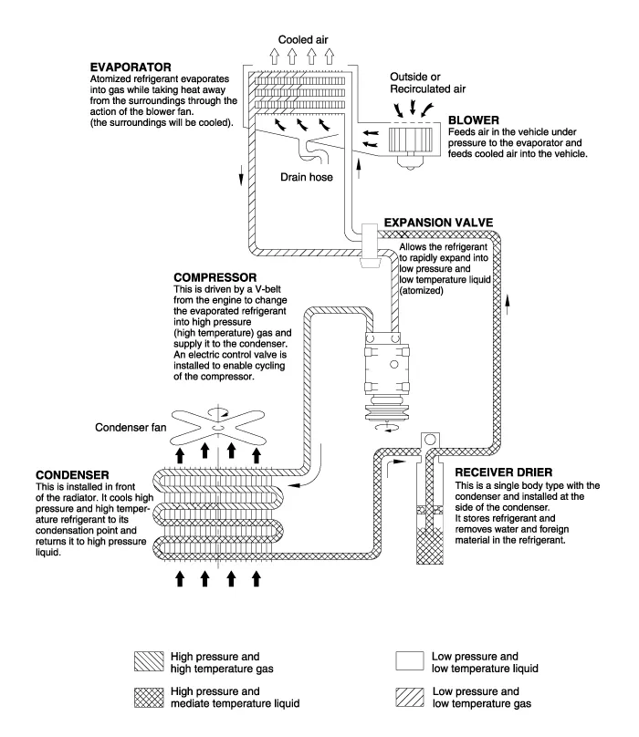
Description and Operation
Repair procedures ➤
Components and Components Location
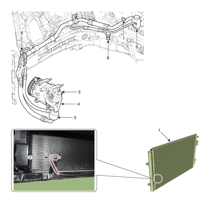
1. Condenser
2. Ambient temperature sensor
3. Suction & Liquid tube assembly
4. Discharge hose
5. Compressor
6. Service port (High pressure)
7. Service port (Low pressure)
8. A/C Pressure transducer (APT)
9. Expansion valve
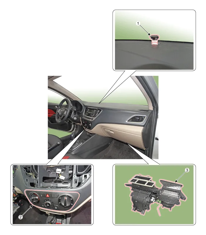
1. Photo sensor
2. Heater & A/C control unit
3. Heater & Blower unit
Compressor oil
1.The R-1234yf system requires synthetic (PAG) compressor oil whereas the R-12 system requires mineral compressor oil. The two oils must never be mixed.
2.Compressor (PAG) oil varies according to compressor model. Be sure to use oil specified for the model of compressor.
1.The oil should be free from moisture, dust, metal powder, etc.
2.Do not mix with other oil.
3.The water content in the oil increases when exposed to air. After use, seal oil from air immediately. (R-1234yf Compressor Oil absorbs moisture very easily.)
4.The compressor oil must be stored in steel containers, not in plastic containers.
Oil total volume in systemFD46XG(IDEMITSU) 110 ± 10cc (3.72 ± 0.34oz.)
1.Open all the doors and engine hood.
2.Start the engine and air conditioning switch to "ON" and set the blower motor control knob at its highest position.
3.Run the compressor for more than 20 minutes between 800 and 1,000 rpm in order to operate the system.
4.Stop the engine.
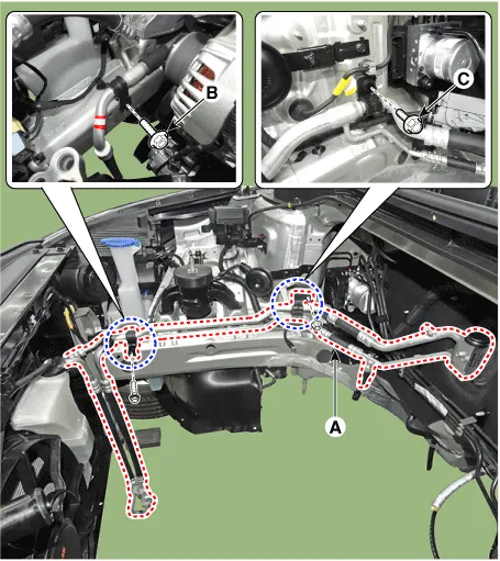
Refrigerant Line
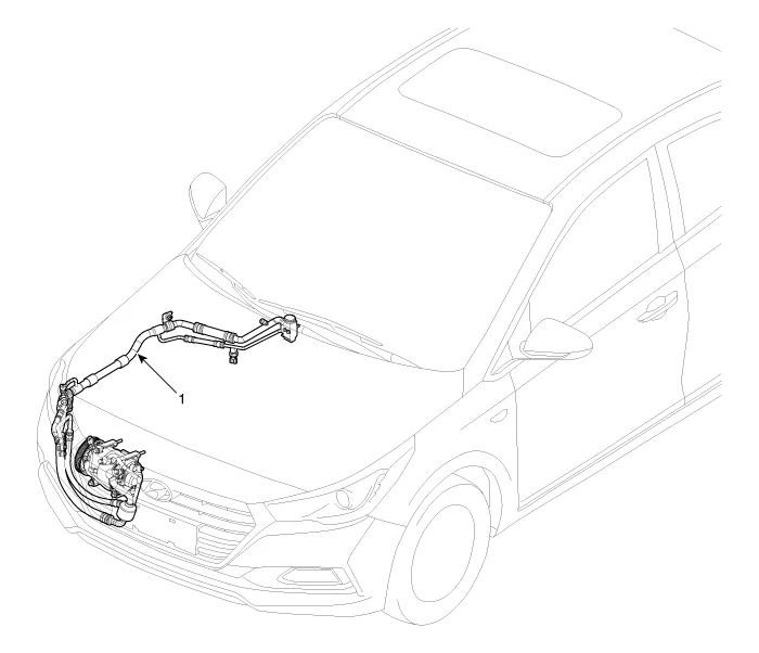
1. Refrigerant line assembly
1.If the compressor is marginally operable, run the engine at idle speed, and let the air conditioning work for a few minutes, then shut the engine off.
2.Disconnect the negative (-) battery terminal.
3.Recover the refrigerant with a recovery / charging station.
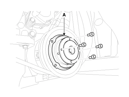
4.Remove the bolts and the expansion valve (A) from the evaporator core.
Tightening torque :8.8 - 13.7 N.m (0.9 - 1.4 kgf.m, 6.5 - 10.1 Ib-ft)
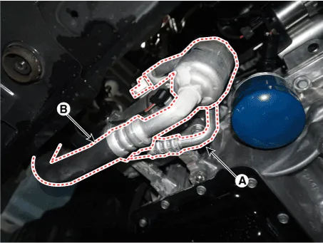
5.Remove the 2 nuts, and then disconnect the discharge line (A) and liquid line (B) from the condenser.
Tightening torque :8.8 - 13.7 N.m (0.9 - 1.4 kgf.m, 6.5 - 10.1 Ib-ft)
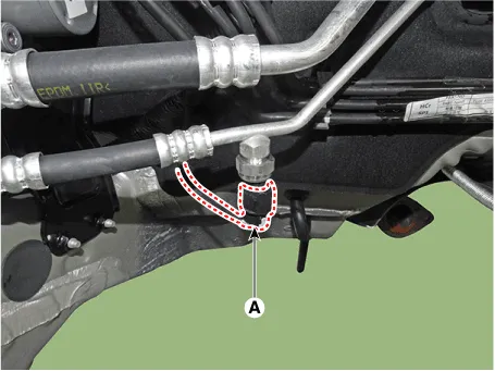
6.Disconnect the A/C pressure transducer connector (A).
7.Remove the engine room under cover.(Refer to Engine Mechanical System - "Engine Room Under Cover")
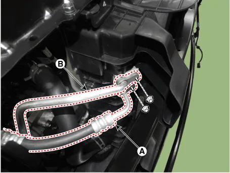
8.Remove the bolts, then disconnect the suction line (A) and discharge line (B) from the compressor.
Tightening torque :21.6 - 32.4 N.m (2.2 - 3.3 kgf.m, 15.9 - 23.9 Ib-ft)

• Plug or cap the lines immediately after disconnecting them to avoid moisture and dust contamination.
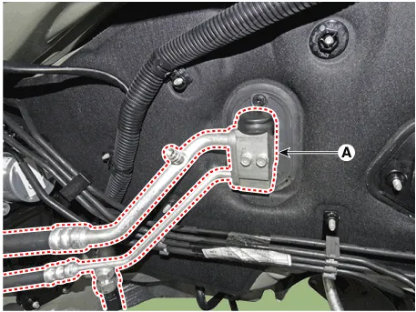
9.Loosen the bracket mounting bolt (B) from suction& liquid assembly (A).
Tightening torque :(B) : 7.8 - 11.8 N.m (0.8 - 1.2 kgf.m, 5.8 - 8.7 Ib-ft)(C) : 8.8 - 13.7 N.m (0.9 - 1.4 khf.m, 6.5 - 10.1 lb-ft)
10.Remove the refrigerant line assembly (A) to the upper of engine room.
11.To install, reverse the removal procedure.

• Plug or cap the lines immediately after disconnecting them to avoid moisture and dust contamination.
• Tighten the bolt or nut joint to the specified torque.
• Using a gas leak detector, check for refrigerant leakage.
• Evacuate air in the refrigeration system and charge system with refrigerant.
Capacity : 480 ± 25 g (16.9 ± 0.88 oz.)
• When replacing and re-installing the A/C system, do not reuse the seal washer. After replacement, please discard components.
Compressor
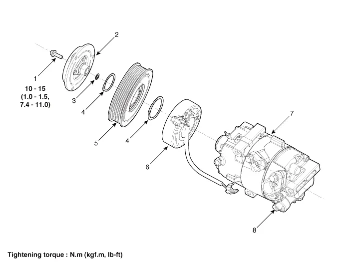
1. Clutch bolt
2. Limiter & Hub assembly
3. Clutch hub spacer
4. Snap ring
5. Pulley
6. Clutch magnetic coil
7. Compressor assembly
8. Electric control valve (ECV)

• Take care not to give physical impact to the plastic pulley.If exposed to the impact of dropping and collision, the pulley should not be used although not damaged.
• Be careful not to place the pulley to downwards of the floor or table.
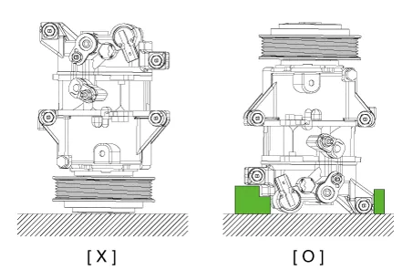
• Be careful not to apply the external force and impact on pulley while moving or using.
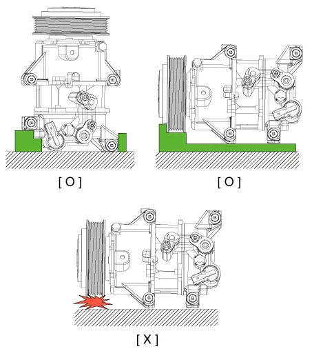
• Be careful not to apply force to the pulley.
1.If the compressor is marginally operable, run the engine at idle speed, and let the air conditioning work for a few minutes, then shut the engine off.
2.Disconnect the negative (-) battery terminal.
3.Recover the refrigerant with a recovery / charging station.
4.Remove the engine room under cover.(Refer to Engine Mechanical System - "Engine Room Cover")
5.Remove the front wheel guard.(Refer to Body - "Front Wheel Guard")
6.Loosen the drive belt.(Refer to Engine Mechanical System - "Drive Belt")
7.Remove the bolts, then disconnect the suction line (A) and discharge line (B) from the compressor.
Tightening torque : 21.6 - 32.4 N.m (2.2 - 3.3 kgf.m, 15.9 - 23.9 Ib-ft)

• Plug or cap the lines immediately after disconnecting them to avoid moisture and dust contamination.

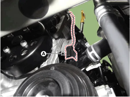
8.Disconnect the compressor switch connector (A).
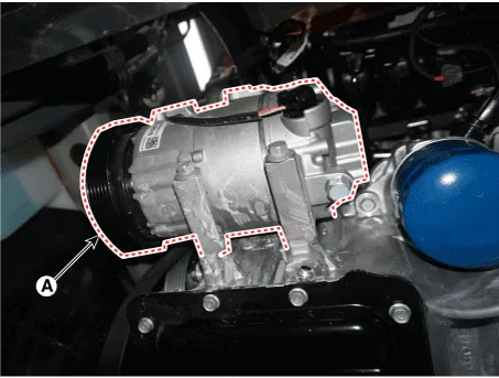
9.Remove the compressor (A) by loosening the mounting bolts.
Tightening torque :19.6 - 33.3 N.m (2.0 - 3.4 kgf.m, 14.5 - 24.6 Ib-ft)
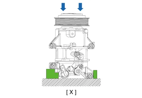
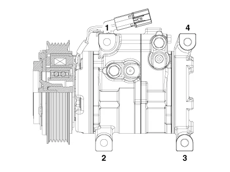
1.Make sure the compressor mounting bolt with the correct length is screwed in. Tighten the mounting bolts with the specified tightening order.
Tightening torque :19.6 - 33.3 N.m (2.0 - 3.4 kgf.m, 14.5 - 24.6 Ib-ft)
2.To install, reverse the removal procedure.

• When replacing and re-installing the A/C system, do not reuse the seal washer. After replacement, please discard components.
• If you install a new compressor, drain all the refrigerant oil from the removed compressor and measure its volume. Subtract the volume of drained oil from the original capacity. The result is the amount of oilcompressor oil you should drain from the new compressor (through the suction fitting).
• Replace the O-rings with new ones at each fitting, and apply a thin coat of refrigerant oil before installing them. Be sure to use the right O-rings for R-1234yf to avoid leakage.
• To avoid contamination, do not return the oil to the container once dispensed, and never mix it with other refrigerant oils.
• Immediately after using the oil, replace the cap on the container and seal it to avoid moisture absorption.
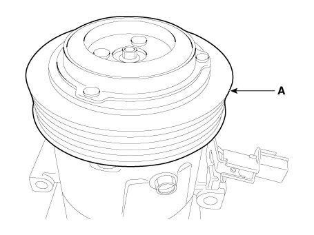
1.Check the plated parts of the limiter & hub assembly for color changes, peeling or other damage. If there is damage, replace the assembly.
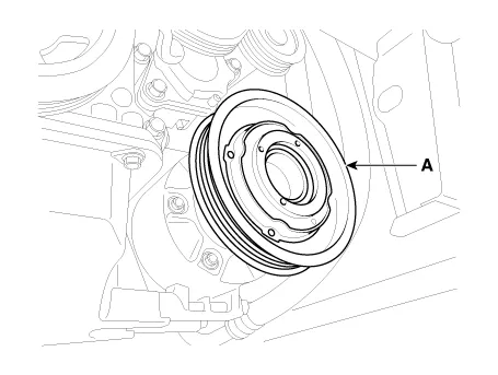
2.Check the pulley (A) bearing play and drag by rotating the pulley by hand. Replace the pulley with a new one if it is noisy or has excessive play / drag.
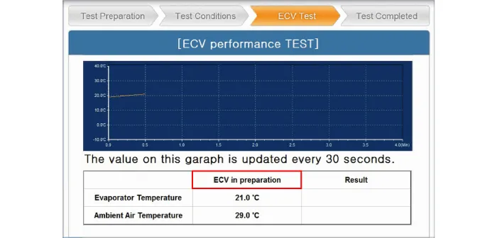
External Control Valve Compressor Inspection (GDS)
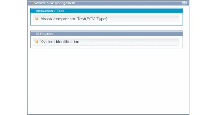
Compressor type: Fixed type compressor, External control valve, Internal control valve.In cases of fixed type and internal control valve, it is possible to inspect compressor's operation with clutch noise. When it comes to External control valve, however, it cannot be checked in this way bacause it doesn't have a clutch. So, ECV should be inspected with GDS as below.1.Connect GDS to the vehicle and select 'Aircon Compressor Test (ECV type)' [ECV1]
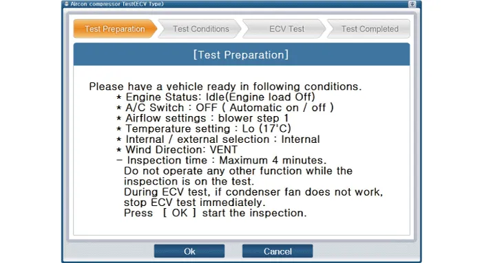
2.Make the vehicle ready as the GDS instruction on the monitor. (Turn off A/C 'switch' only)[ECV2]

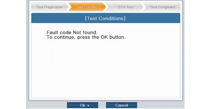
3.Check if other DTC codes are found before inspect ECV compressor. If so, solve that problems first. If not, press 'OK' button to continue.

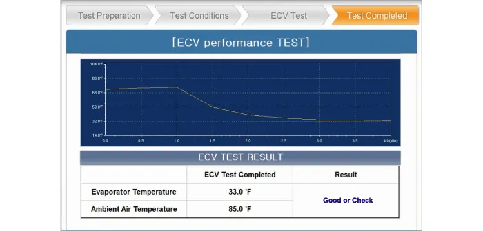
4. Start inspection[ECV5]


5. Check the result of inspection and click 'Check Detail' if it's 'Check'. Follow the instruction and inspect ECV again from the first step. [ECV7]

1.Remove the engine room under cover.(Refer to Engine Mechanical System - "Engine Room Cover")
2.Remove the front wheel guard.(Refer to Body - "Front Wheel Guard")
3.Loosen the drive belt.(Refer to Engine Mechanical System - "Drive Belt")
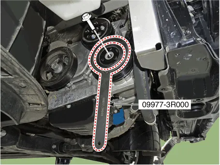
4.Remove the clutch bolt while holding the pulley with a clutch bolt remover (09977-29000).
Tightening torque :10.0 - 15.0 N.m (1.02 - 1.53 kgf.m, 7.37 - 11.0 lb-ft)
5.Loossen the limiter bolts and then remove the limiter & hub assembly (A).
6.Remove the pulley (B) after removing the snap ring (A) with a snap ring plier.
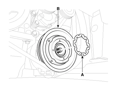

• Be careful not to damage the pulley and compressor during disassembly / reassembly.
• Once the snap ring is removed, replace it with a new one.
7.Reassemble in the reverse order of disassembly.

• Clean the pulley and compressor sliding surfaces with non-petroleum solvent.
• Install a new snap ring, and make sure they are fully seated in the groove.
• Make sure that the pulley turns smoothly after reassembly.
Condenser
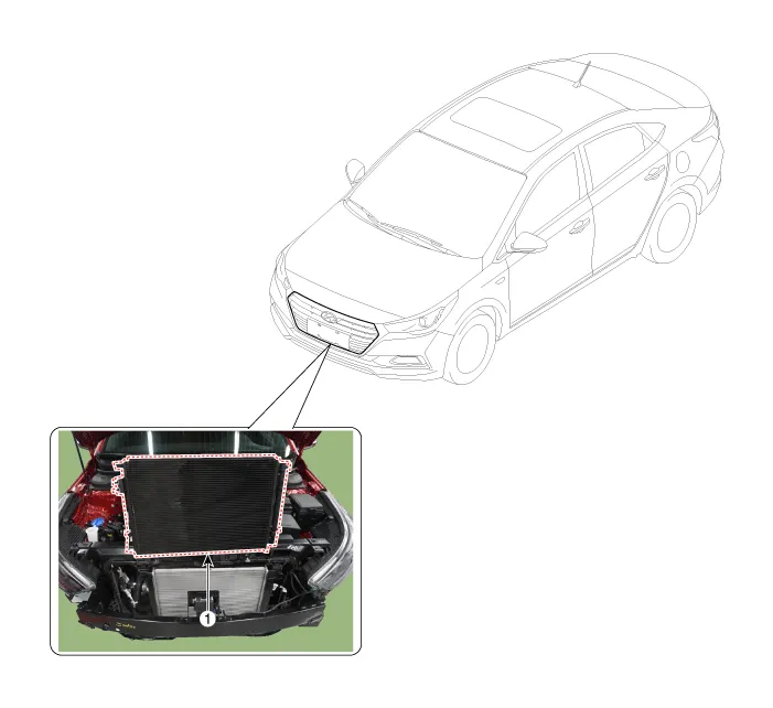
1. Condenser
1.Check the condenser fins for clogging and damage. If clogged, clean them with water, and blow them with compressed air. If bent, gently bend them using a screwdriver or pliers.
2.Check the condenser connections for leakage, and repair or replace it, if required.
1.Recover the refrigerant with a recovery / recycling / charging station.
2.Disconnect the negative (-) battery terminal.
3.Remove the front bumper.(Refer to Body - "Front Bumper Cover")
4.Remove the horn.(Refer to Body Electrical System - "Horn")
5.Remove the upper air guard.(Refer to Engine Mechanical System - "Cooling Fan")
6.Remove the nuts, and then disconnect the discharge line (A) and liquid line (B) from the condenser.
Tightening torque :8.8 - 13.7 N.m (0.9 - 1.4 kgf.m, 6.5 - 10.1 lb-ft)

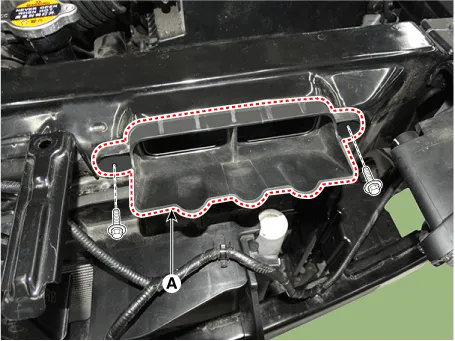
7.Loosen the mounting pin - type retainers and bolts, remove the side air guard (A).
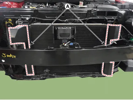
8.After loosening the mounting bolts, remove the intake shield (A).
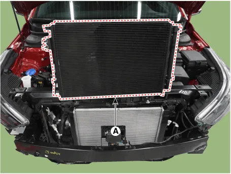
9.Remove the condenser (A) from radiator.
10.To install, reverse the removal procedure.

• When replacing and re-installing the A/C system, do not reuse the seal washer. After replacement, please discard components.
• If you're installing a new condenser, add refrigerant oil.
• Replace the O-rings with new ones at each fitting, and apply a thin coat of refrigerant oil before installing them. Be sure to use the right O-rings for R-1234yf to avoid leakage.
• Be careful not to damage the radiator and condenser fins when installing the condenser.
• Charge the system, and test its performance.
Receiver-Drier
1.Remove the condenser.
2.Remove the cap (A) on the bottom of the condenser with a L wrench.
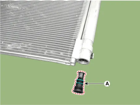
Tightening torque :2.8 - 3.3 N.m (0.29 - 0.34 kgf.m, 2.1 - 2.5 lb-ft)
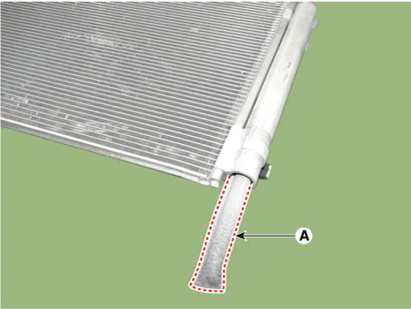
3.Remove the receiver - drier (A) from condenser using a long nose plier. Check for crumbled receiver - drier and clogged bottom cap filter.
4.Apply air conditioning compressor oil along the O-rings and threads of the new bottom cap.
5.Insert a new receiver-drier into the receiver drier tank. The receiver-drier must be sealed in vacuum before it is exposed to air for use.
6.Install a new bottom cap to the condenser.

• When replacing and re-installing the A/C system, do not reuse the seal washer. After replacement, please discard components.
• Always replace the receiver-drier and bottom cap at the same time.
• Be careful not to damage the radiator and condenser fins when installing the condenser.
• Charge the system, and test its performance.
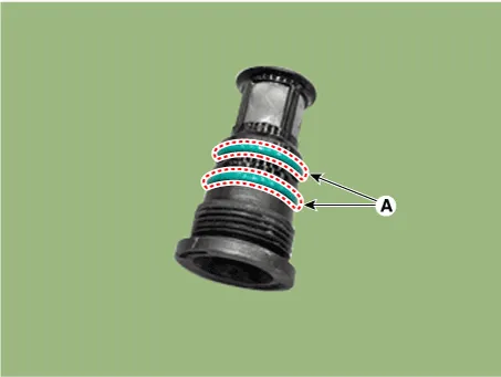
• Replace the O-rings (A) with new ones at each fitting, and apply a thin coat of refrigerant oil before installing them. Be sure to use the right O-rings (A) for R-1234yf to avoid leakage.
A/C Pressure Transducer
![]()
• Before measuring the pressure of the refriferant line, check whether the refrigerant amount is charged in accordance with the specified charging amount.(Refer to Heating, Ventilation, Air Conditioning - "Specifications")
1.Turn the ignition switch OFF.
2.Install the refrigerant recovery/recycling/charging system.(Refer to Air Conditioning System - "Repair procedures")
3.Turn ON the ignition switch, put into operation the air conditioner.
4.Calculate the reference voltage of the Recovery/Recycle/Recharge machine high pressure value using the formula below.
Reference voltage (V) = 0.0088 * pressure(psi) + 0.37
5.Measure the sensor output voltage between terminal "1" and "2".
![]()
| Pin No | Function |
| 1 | Ground |
| 2 | Voltage |
| 3 | Power (+5V) |
6.If the reference voltage value and the sensor output voltage value are close to each other, the air conditioner pressure transducer is normal.
7.If 0V is output or the reference voltage value and sensor output voltage value are not close to each other, replace the air conditioner pressure transducer.
![]()
• Check if the output voltage changes when the high pressure value of the refrigerant line changes.
![]()
1.The heating, ventilation and air conditioning can be quickly diagnosed failed parts with vehicle diagnostic system (GDS).※ The diagnostic system (GDS) provides the following information.(1) Self diagnosis : Checking the failure code (DTC) and display.(2) Current data : Checking the system input / output data state.(3) Actuation test : Checking the system operation condition.(4) Additional function : Other controlling such as he system option and zero point adjustment.
2.Select the 'Car model' and the system to be checked in order to check the vehicle with the tester.
3.Select the 'Current data' menu to search the current state of the input / output data.The input / output data for the sensors corresponding to the A/C Pressure Transducer can be checked.
![]()
1.Disconnect the negative (-) battery terminal.
2.Recover the refrigerant with a recovery/charging station.
3.Disconnect the A/C pressure transducer connector (A).
![]()
4.Remove the A/C pressure transducer (A).
Tightening torque :10.0 - 12.0 N.m (1.02 - 1.22 kgf.m, 7.38 - 8.82 lb-ft)
![]()
![]()
5.To install, reverse the removal procedure.
![]()
Evaporator Temperature Sensor
1.Turn the ignition switch OFF.
2.Disconnect the evaporator temperature sensor connector.
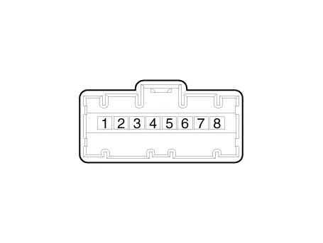
3.Measure the resistance between terminal "+" and "-" of the evaporator temperature sensor.
| Evaporator core temperature [°C (°F)] | Resistance [KΩ] | Voltage [V] |
| -10 (14) | 43.35 | 2.96 |
| 0 (32) | 27.62 | 2.4 |
| 10 (50) | 18.07 | 1.88 |
| 20 (68) | 12.11 | 1.44 |
| 30 (86) | 8.30 | 1.08 |
| 40 (104) | 5.81 | 0.81 |
1. Sensor Ground
2. Evaporator sensor (+)
1.The heating, ventilation and air conditioning can be quickly diagnosed failed parts with vehicle diagnostic system (GDS).※ The diagnostic system (GDS) provides the following information.(1) Self diagnosis : Checking the failure code (DTC) and display.(2) Current data : Checking the system input / output data state.(3) Actuation test : Checking the system operation condition.(4) Additional function : Other controlling such as he system option and zero point adjustment.
2.Select the 'Car model' and the system to be checked in order to check the vehicle with the tester.
3.Select the 'Current data' menu to search the current state of the input / output data.The input / output data for the sensors corresponding to the Evaporator Temperature Sensor can be checked.
1.Disconnect the negative (-) battery terminal.
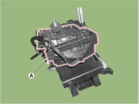
2.Remove the heater and blower unit from the crash pad after loosening the mounting nuts.(Refer to Heater - "Heater Unit")
3.Remove the evaporator core cover (A) after loosening the mounting screws.
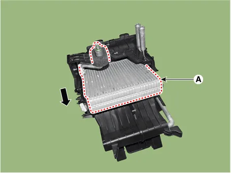
4.Pull out the evaporator core (A) from the heater unit.
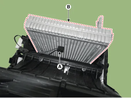
5.Remove the evaporator temperature sensor (A) from the evaporator core.
6.To install, reverse the removal procedure.

• If you're installing a new heater core, add refrigerant oil (PAG OIL).
• Replace the O-rings with new ones at each fitting, and apply a thin coat of refrigerant oil before installing them. Be sure to use the right O-rings for R-1234yf to avoid leakage.
• Immediately after using the oil, replace the cap on the container, and seal it to avoid moisture absorption.
• Do not spill the refrigerant oil on the vehicle ; it may damage the paint, if the refrigerant oil contacts the paint, wash it off immediately.
• Apply sealant to the grommets.
• Make sure that there is no air leakage.
• Charge the system and test its performance.
• Do not interchange the inlet and outlet heater hoses and install the hose clamps securely.
In-car Sensor
1.The heating, ventilation and air conditioning can be quickly diagnosed failed parts with vehicle diagnostic system (GDS).※ The diagnostic system (GDS) provides the following information.(1) Self diagnosis : Checking the failure code (DTC) and display.(2) Current data : Checking the system input / output data state.(3) Actuation test : Checking the system operation condition.(4) Additional function : Other controlling such as he system option and zero point adjustment.
2.Select the 'Car model' and the system to be checked in order to check the vehicle with the tester.
3.Select the 'Current data' menu to search the current state of the input / output data.The input / output data for the sensors corresponding to the In - car Sensor can be checked.

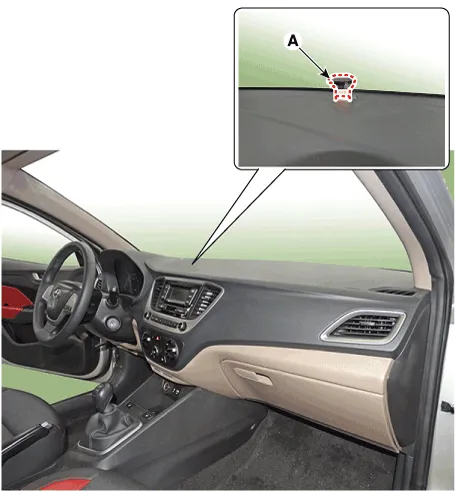
Photo Sensor
1.Turn the ignition switch ON.
2.Connect the GDS.
3.Emit intensive light toward the photo sensor using a lamp, and check the output voltage change.
4.The voltage will rise with higher intensive light and reduce with lower intensive light.
1. Auto light signal
2. Auto light ground
3. Photo signal (RH)
4. LED power (B+)
5. LED ground (To BCM)
6. Photo signal (LH)
7. Photo power
8. Auto light power (5V)
1.Disconnect the negative (-) battery terminal.
2.Using a screwdriver or remover, remove the photo sensor (A).
3.To install, reverse the removal procedure.
Ambient Temperature Sensor
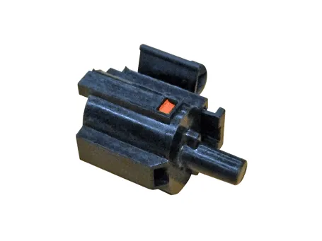

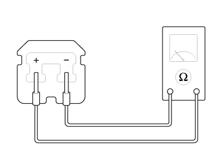
1.Check the resistance of the ambient temperature sensor between terminals 1 and 2 whether it changes by changing the ambient temperature.
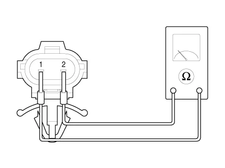
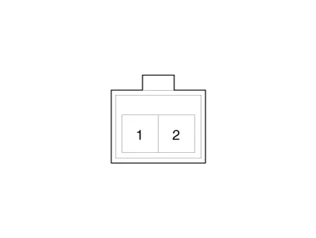
1. Ambient Sensor (+)
2. Sensor ground
| Ambient temperature [°C (°F)] | Resistance between terminal 1 and 2 (kΩ) |
| -30 (-22) | 480.41 |
| -20 (-4) | 271.21 |
| -10 (14) | 158.18 |
| 0 (32) | 95.096 |
| 10 (50) | 58.799 |
| 20 (68) | 37.315 |
| 30 (86) | 24.26 |
| 40 (104) | 16.13 |
| 50 (122) | 10.95 |
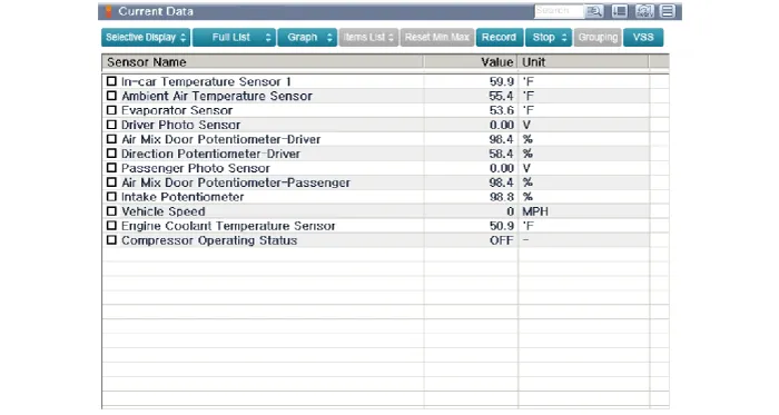
1.The heating, ventilation and air conditioning can be quickly diagnosed failed parts with vehicle diagnostic system (GDS).※ The diagnostic system (GDS) provides the following information.(1) Self diagnosis : Checking the failure code (DTC) and display.(2) Current data : Checking the system input / output data state.(3) Actuation test : Checking the system operation condition.(4) Additional function : Other controlling such as he system option and zero point adjustment.
2.Select the 'Car model' and the system to be checked in order to check the vehicle with the tester.
3.Select the 'Current data' menu to search the current state of the input / output data.The input / output data for the sensors corresponding to the Ambient Temperature Sensor can be checked.

1.Disconnect the negative (-) battery terminal.
2.Remove the engine room under cover.(Refer to Engine Mechanical System - "Engine Room Cover")
3.Disconnect the connector (A) and then remove the ambient temperature sensor (B).
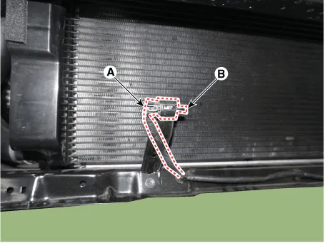
4.To install, reverse the removal procedure.


Other information:
Hyundai Accent (HC) (2017 - 2022) Service Manual: LCD Display Modes
The information provided may differ depending on which functions and options are available for your specific Hyundai Accent configuration. Engage parking brake to edit settings/Shift to P to edit settings This warning message appears if you attempt to adjust User Settings while driving. - Manual transmission For your safety, change User Settings only after parking the vehicle, applying the parking brake, and moving the shift lever to neutral.
Contents
- General Safety Information and Caution
- Description and Operation
- Repair procedures
- Components and Components Location
- Compressor oil
- Refrigerant Line
- Compressor
- Condenser
- Receiver-Drier
- A/C Pressure Transducer
- Evaporator Temperature Sensor
- In-car Sensor
- Photo Sensor
- Ambient Temperature Sensor
Categories
- Manuals Home
- Hyundai Accent Owners Manual
- Hyundai Accent Service Manual
- Questions & Answers
- Video Guides
- Useful Resources
- New on site
- Most important about car
- Privacy Policy

0.0091