Hyundai Accent (HC): Heater / Temperature Control Actuator
1. Temperature control actuator
| Door Position | Voltage (V) | Error Detecting |
| Max. cooling | 0.3 ± 0.15 | Low voltage : 0.1V or less High voltage : 4.9V or more |
| Max. heating | 4.7 ± 0.15 |
1.Turn the ignition switch OFF.
2.Disconnect the temperature control actuator connector.
3.Verify that the temperature control actuator operates to the cool position when connecting 12V to terminal 6 and grounding terminal 5.Verify that the temperature control actuator operates to the warm position when connected in reverse.
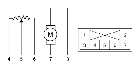
| Pin NO | Function |
| 1 | - |
| 2 | - |
| 3 | Warm position |
| 4 | Sensor ground |
| 5 | Feedback signal |
| 6 | Sensor (+5V) |
| 7 | Cool position |
4.Connect the temperature control actuator connector.
5.Turn the ignition switch ON.
6.Check the voltage between terminal 5 and 6.
7.If the measured voltage is not within specification, check the operation by replacing the existing temperature control actuator with a new genuine part. After that, determine whether replacement of the temperature control actuator is required or not.
1.The heating, ventilation and air conditioning can be quickly diagnosed failed parts with vehicle diagnostic system (GDS).※ The diagnostic system (GDS) provides the following information.(1) Self diagnosis : Checking the failure code (DTC) and display.(2) Current data : Checking the system input / output data state.(3) Actuation test : Checking the system operation condition.(4) Additional function : Other controlling such as he system option and zero point adjustment.
2.Select the 'Car model' and the system to be checked in order to check the vehicle with the tester.
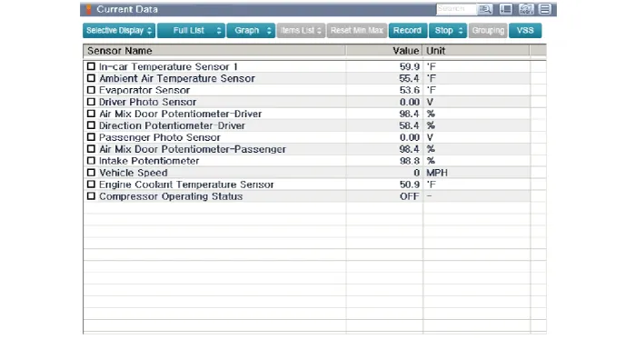
3.Select the 'Current data' menu to search the current state of the input / output data.The input / output data for the sensors corresponding to the Temperature Control Actuator can be checked.
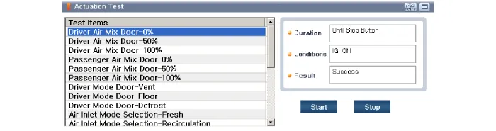
4.To perform compulsory operation on Temperature Control Actuator input factors, select "ACTUATION TEST".
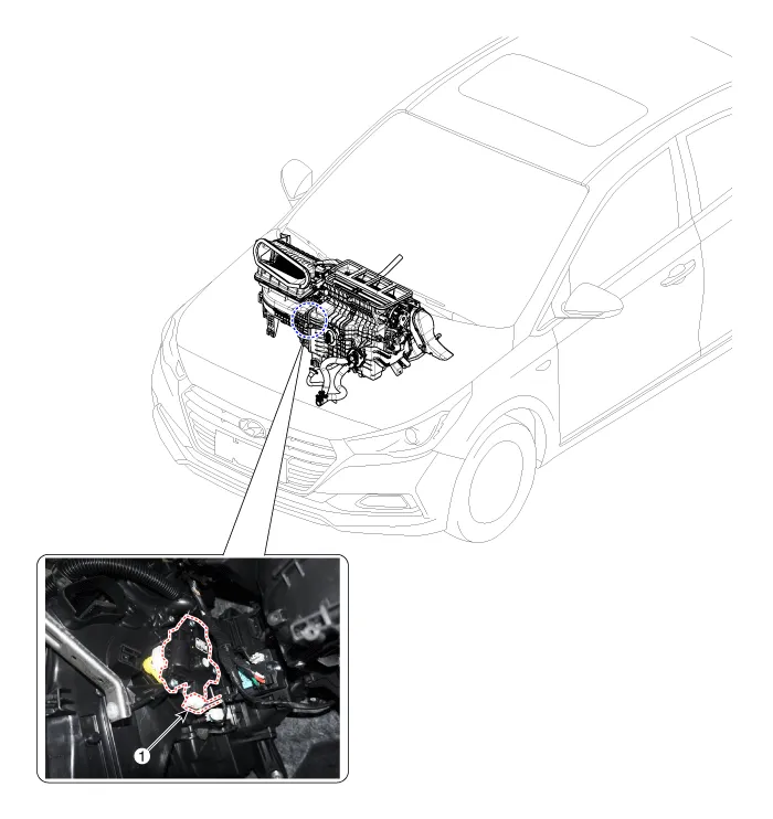
1.Disconnect the negative (-) battery terminal.
2.Remove the glove box upper cover housing assembly.(Refer to Body - "Glove Box Upper Cover Housing Assembly")
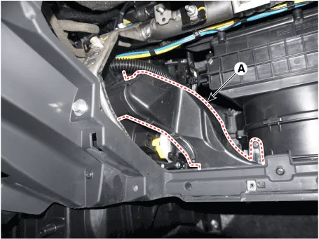
3.Remove the passenger's side shower duct (A) after loosening the screw.
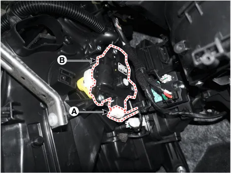
4.Disconnect the connector (A) and then remove the temperature control actuator (B) after loosening the mounting screws.
5.To install, reverse the removal procedure.


Other information:
Hyundai Accent (HC) (2017 - 2022) Service Manual: General Tightening Torque Table
- Tightening Torque Table of Standard Parts BOLT (Nominal diameter) NUT (Nominal diameter) BOLT/NUT Normal screw Torque Nm (kg.m, Ib-ft) Nominal diameter.Hyundai Accent (HC) (2017 - 2022) Service Manual: Description and Operation
- Description Burglar Alarm State [B/A State] B/A StateDescription DISARM1) In "DISARM" state, no vehicle start inhibition. So, when door, hood, or Tailgate is opened, there is no alarm sound and flashing. 2) If the battery is disconnected while the state is not "ARM/ARMWAIT/ALARM/REARM", B/A state is set to "DISARM" state. 3)In "DISARM" state, security indicator keeps blinking.
Categories
- Manuals Home
- Hyundai Accent Owners Manual
- Hyundai Accent Service Manual
- Questions & Answers
- Video Guides
- Useful Resources
- New on site
- Most important about car
- Privacy Policy

0.0058