Hyundai Accent (HC): Emission Control System
Contents:
- Specifications
- Description and Operation
- Troubleshooting
- Schematic Diagrams
- Components and Components Location
- Evaporative Emission Control System
- Exhaust Emission Control System
Specifications
| Item | Specification |
| Coil Resistance (Ōä”) | 12.5 ~ 16.5 [20┬░C (68┬░F)] |
| Item | kgf.m | N.m | lb-ft |
| Positive Crankcase Ventilation (PCV) valve | 1.0 - 1.2 | 9.8 - 11.7 | 2.2 - 2.6 |
| Canister mounting bolt | 2.2 - 2.4 | 21.5 - 23.5 | 4.8 - 5.2 |
| Exhaust manifold hit protecter mounting bolt | 1.0 - 1.2 | 9.8 - 11.7 | 2.2 - 2.6 |
| EGR cooler pipe mounting bolt | 1.9 - 2.4 | 18.6 - 23.5 | 4.1 - 5.2 |
| Exhaust manifold & Catalytic Converter stay mounting bolt | 4.0 - 5.0 | 39.2 - 49.0 | 8.8 - 11.0 |
| Engine mounting support braket mounting nut | 9.0 - 11.0 | 88.2 - 107.8 | 19.8 - 24.2 |
| Engine mounting support braket mounting bolt / nut | 6.0 - 7.5 | 58.8 - 73.5 | 13.2 - 16.5 |
| Exhaust manifold & Catalytic Converter mounting nut | 3.0 - 4.0 | 29.4 - 39.2 | 6.6 - 8.8 |
| Catalytic Converter & Center muffler mounting nut | 4.0 - 6.0 | 39.2 - 58.8 | 8.8 - 13.2 |
Description and Operation
ŌĆó The Crankcase Emission Control System prevents blow-by gas from releasing into the atmosphere. This system recycles gas back into the intake manifold (Closed Crankcase Ventilation Type).
ŌĆó The Evaporative Emission Control System prevents evaporative gas from releasing into the atmosphere. This system burns gas at appropriate engine operating condition after gathering it in the canister.
ŌĆó The Exhaust Emission Control System converts the three pollutants [hydrocarbons (HC), carbon monoxide (CO), and oxides of nitrogen (NOx)] into harmless substances by using the 3-way catalytic converter.
Troubleshooting
| Symptom | Suspect area |
| Engine will not start or struggle to start | Vapor hose damaged or disconnected |
| Engine struggles to start | Malfunction of the Purge Control Solenoid Valve |
| Rough idle or engine stalls | Vapor hose damaged or disconnected |
| Malfunction of the PCV valve | |
| Rough idle | Malfunction of the Evaporative Emission Control System |
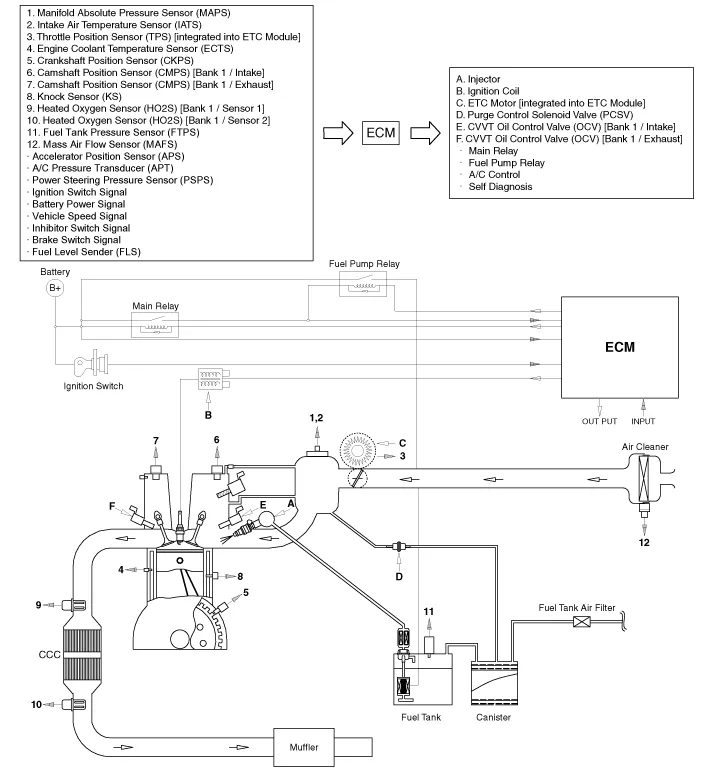
Schematic Diagrams
Components and Components Location
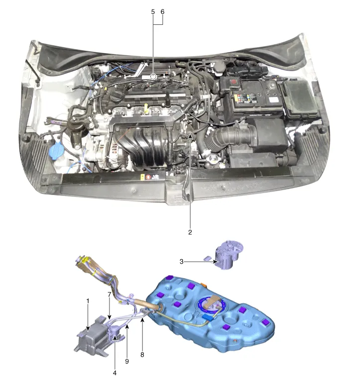
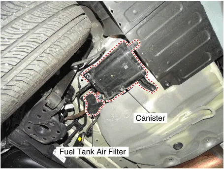
1. Canister
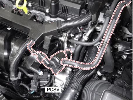
2. Purge Control Solenoid Valve (PCSV)
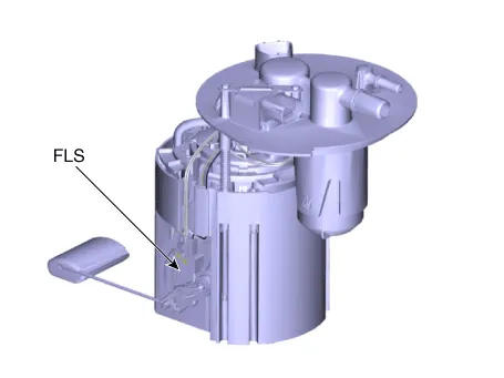
3. Fuel Level Sensor (FLS)
4. Fuel Tank Air Filter
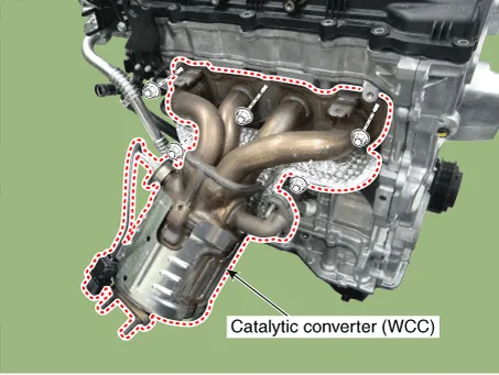
5. Catalytic converter (WCC)
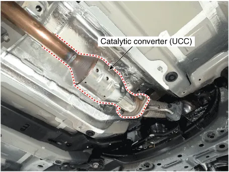
6. Catalytic converter (UCC)
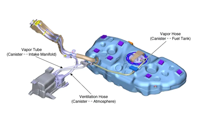
7. Vapor Tube (Canister Ōåö Intake Manifold)
8. Vapor Hose (Canister Ōåö Fuel Tank)
9. Ventilation Hose (Canister Ōåö Atmosphere)
| 1. Canister 4. Fuel Tank Air Filter | 2. Purge Control Solenoid Valve (PCSV) |
|
|
| 3. Fuel Level Sensor (FLS) | 5. Catalytic converter (WCC) |
|
|
| 6. Catalytic converter (UCC) | |
| |
| 7. Vapor Tube (Canister Ōåö Intake Manifold) 8. Vapor Hose (Canister Ōåö Fuel Tank) 9. Ventilation Hose (Canister Ōåö Atmosphere) | |
| |
Evaporative Emission Control System ➤
Exhaust Emission Control System ➤


Other information:
Forward Collision-Avoidance Assist is designed to help reduce or help avoid accident risk. It recognizes the distance to the vehicle ahead through sensors (for example, radar), and, if necessary, warns the driver or applies emergency braking. ŌØł Radar type FCA does not recognize for pedestrians in front. WARNING Forward Collision-avoidance Assist is a supplemental system and is not a substitute for safe driving practices.The Smartstream Intelligent Variable Transmission (Smartstream IVT) in the Hyundai Accent automatically adjusts its driving ratios based on vehicle speed and accelerator pedal position. The appropriate ŌĆ£speedŌĆØ (ratio) is selected automatically according to the shift lever position and current driving conditions, helping deliver smooth acceleration and efficient performance.
Contents
- Specifications
- Description and Operation
- Troubleshooting
- Schematic Diagrams
- Components and Components Location
- Evaporative Emission Control System
- Exhaust Emission Control System
Categories
- Manuals Home
- Hyundai Accent Owners Manual
- Hyundai Accent Service Manual
- Questions & Answers
- Video Guides
- Useful Resources
- New on site
- Most important about car
- Privacy Policy

0.0115