Hyundai Accent (HC): Emission Control System / Evaporative Emission Control System
Contents:
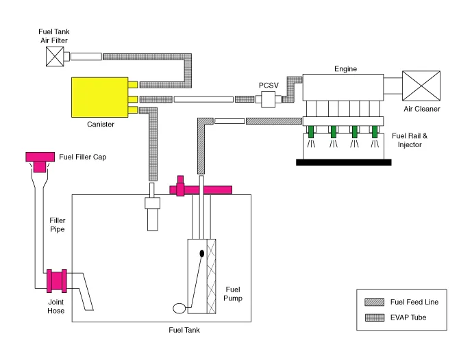
Schematic Diagrams
Repair procedures
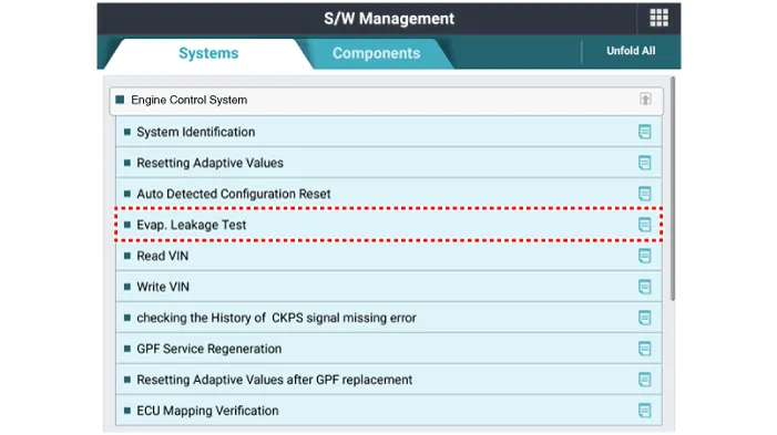
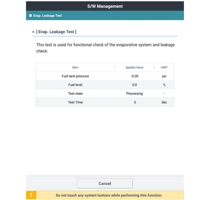
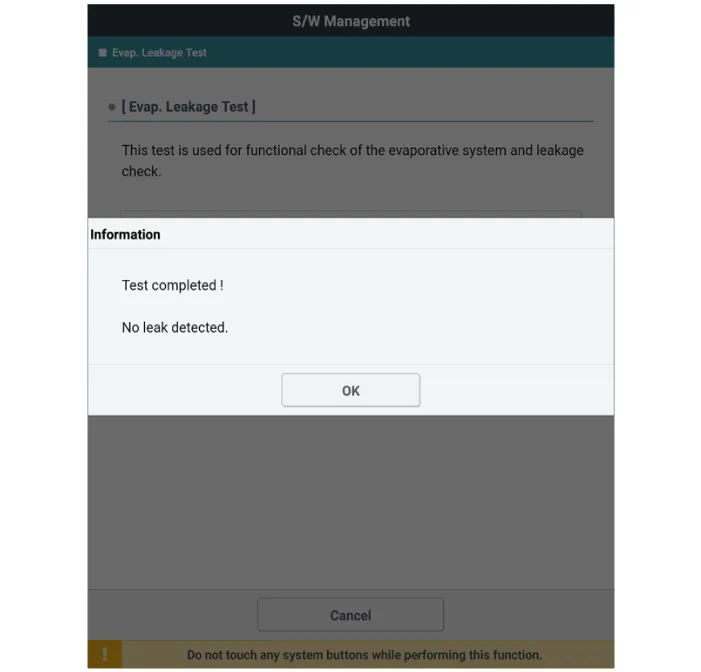
1.Select "Evap. Leakage Test".
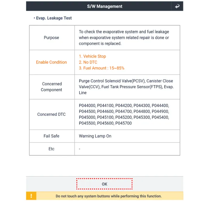
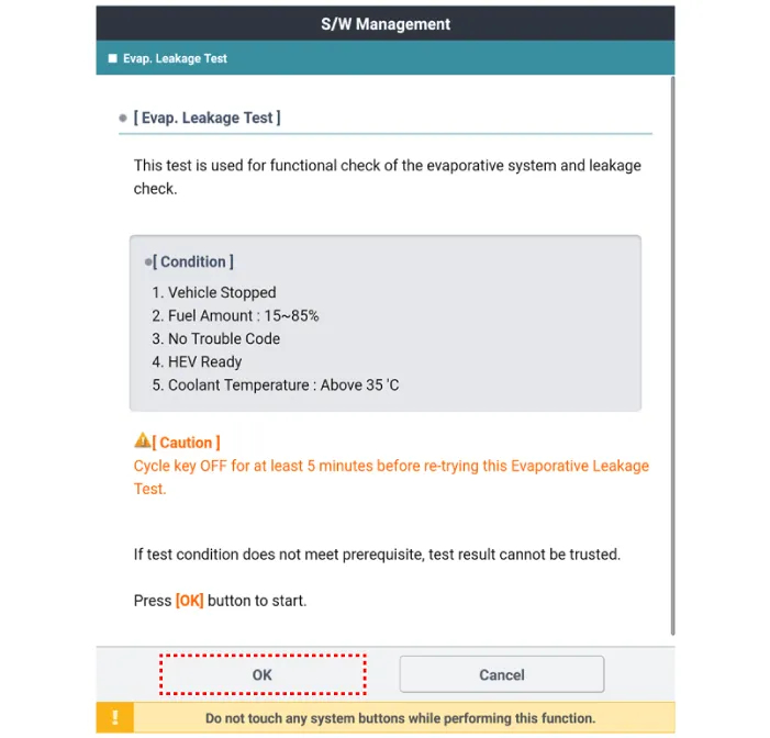
2.The test shall be conducted in accordance with GDS instructions.
Canister
1.Turn the ignition switch OFF and disconnect the battery negative (-) cable.
2.Lift the vehicle.
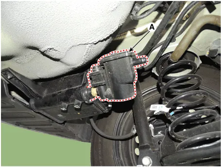
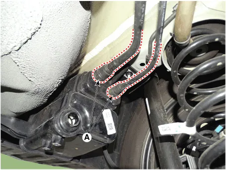
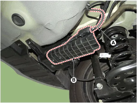
3.Disconnect the canister close velve extension connector (A).
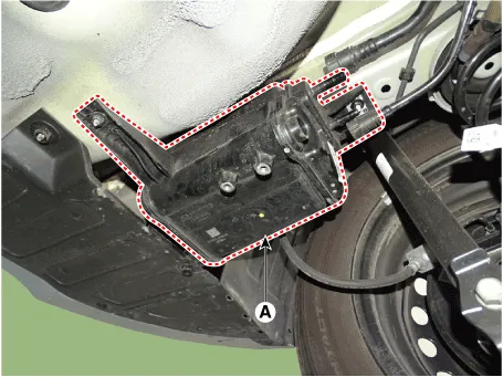
4. Remove the canister protector (B).

5.Disconnect the canister close velve connector (A).
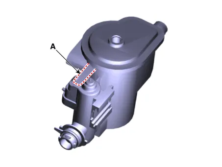
6.Remove the ventilation hose (B).
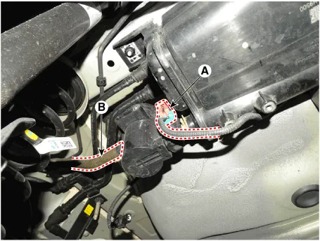
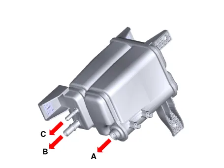
7.Remove the air filter (A).
8.Disconnect the vapor hose quick-connector (A).
9.Remove the canister assembly (A) after loosening the bolt and nut.
Canister installation bolt :19.6 - 29.4 N.m (2.0 - 3.0 kgf.m, 14.5 - 21.7 lb-ft)
1.Check for the following items visually.
– Cracks or leakage of the canister
– Loose connection, distortion, or damage of the vapor hose/ tube
1.Install in the reverse order of removal.
Fuel Filler Cap
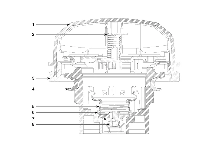
1. Cover
2. Torsion spring
3. Retainer
4. Gasket seal
5. Spring
6. Plate seal
7. Vacuum valve
8. Spring
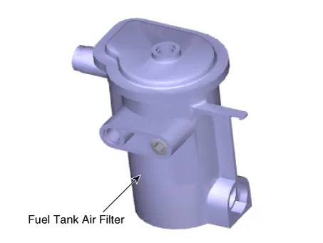
Fuel Tank Air Filter
1.Turn the ignition switch OFF and disconnect the battery negative (-) cable.
2.Lift the vehicle.
3.Disconnect the canister close velve extension connector (A).
4. Remove the canister protector (B).
5.Disconnect the canister close velve connector (A).
6.Remove the ventilation hose (B).

7.Remove the air filter (A).

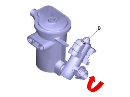
8.Release the lever (A), and then separate the canister close valve (B) from the fuel tank air filter after rotating it in the direction of the arrow in the figure.


Other information:
Hyundai Accent (HC) (2017 - 2022) Service Manual: Description and Operation
- Description Burglar Alarm State [B/A State] B/A StateDescription DISARM1) In "DISARM" state, no vehicle start inhibition. So, when door, hood, or Tailgate is opened, there is no alarm sound and flashing. 2) If the battery is disconnected while the state is not "ARM/ARMWAIT/ALARM/REARM", B/A state is set to "DISARM" state. 3)In "DISARM" state, security indicator keeps blinking.
Contents
Categories
- Manuals Home
- Hyundai Accent Owners Manual
- Hyundai Accent Service Manual
- Questions & Answers
- Video Guides
- Useful Resources
- New on site
- Most important about car
- Privacy Policy

0.0059