Hyundai Accent (HC): Heating, Ventilation and Air Conditioning / Blower
Contents:
Blower Unit
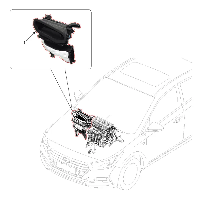
1. Blower unit assembly
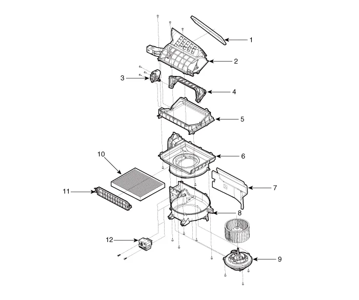
1. Seal
2. Intake duct case
3. Intake actuator
4. Intake door
5. Intake lower case
6. Blower upper case
7. Blower unit pad
8. Blower lower case
9. Blower motor
10. Air filter
11. Air filter cover
12. PWM Blower module

1.Disconnect the negative (-) battery terminal.
2.Recover the refrigerant with a recovery / recycling / charging station.
3.When the engine is cool, drain the engine coolant from the radiator.(Refer to Engine Mechanical System - "Coolant")
4.Remove the cowl top cover.(Refer to Body - "Cowl Top Cover")
5.Remove the bolts and the expansion valve (A) from the evaporator core.
Tightening torque : 8.8 - 13.7 N.m (0.9 - 1.4 kgf.m, 6.5 - 10.1 Ib-ft)


• Plug or cap the lines immediately after disconnecting them to avoid moisture and dust contamination.
• When installing, replace with a new O-ring.
6.Disconnect the heater hoses (A) from the heater unit.


• Engine coolant will run out when the hoses are disconnected; drain it into a clean drip pan. Be sure not to let coolant spill on electrical parts or painted surfaces. If any coolant spills, rinse it off immediately.
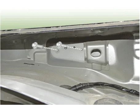
7.Loosen the cowl cross member mounting bolts.
Tightening torque : 16.7 - 25.5 N.m (1.7 - 2.6 kgf.m, 12.3 -18.8 lb-ft)
8.Remove the floor console assembly.(Refer to Body - "Floor Console Assembly")
9.Remove the crash pad lower panel.(Refer to Body - "Crash Pad Lower Panel")
10.Remove both sides of the front pillar trim.(Refer to Body - "Front Pillar Trim")
11.Remove the cowl side trim.(Refer to Body - "Cowl Side Trim")
12.Remove the steering column shroud lower panel.(Refer to Body - "Steering Column Shroud Panel")
13.Remove the steering wheel.(Refer to Steering System - "Steering Wheel")
14.Remove the multifunction switch.(Refer to Body Electrical System - "Multifunction Switch")
15.Lower the steering column after loosening the mounting bolts.(Refer to Steering System - "Steering Column and Shaft")
16.Remove the shift lever assembly.(Refer to Automatic Transmission System - "Shift Lever")
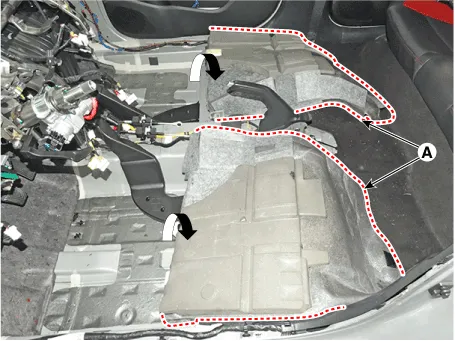
17.Remove the rear air duct (A).
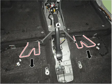
18.Separate the floor carpet (A) to obtain space for removing the rear heating duct.
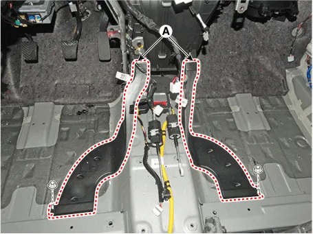
19.Loosen the mounting nuts and remove the front air duct (A).
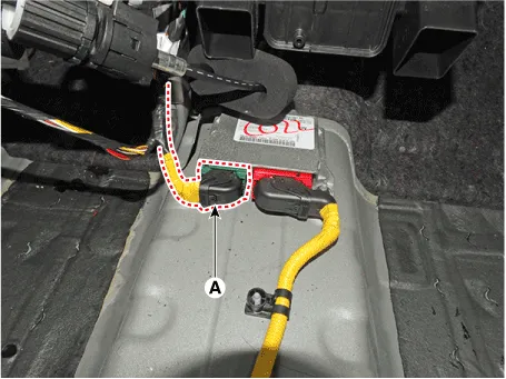
20.Disconnect the airbag control module (SRSCM) connector (A).
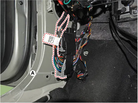
21.Disconnect the junction box connectors (A).

22.Disconnect the multi box connectors (A).[Driver's side]

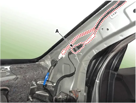
23.Disconnect the connectors (A) and the mounting clips in the front pillar.
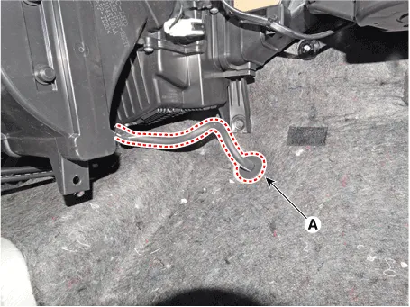
24.Remove the drain hose (A).
25.Loosen the cowl blower unit mounting bolts.
Tightening torque :3.9 - 5.9 N.m (0.4 - 0.6 kgf.m, 2.9 - 4.3 Ib-ft)

26.After loosening the bolts and nuts remove the main crash pad and cowl cross bar assembly (A) together.

27.Disconnect the heater & blower unit connectors.
(1)Disconnect the mode actuator connector (A) and remove the wiring mounting clips.
(2)Disconnect the auto defogging actuator connector (A) and intake actuator connector (B) remove the wiring mounting clips.
(3)Disconnect the temperature control actuator (A), power mosfet connector (B) and remove the wiring mounting clips.
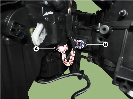
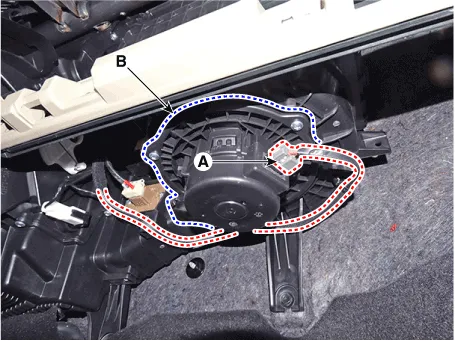
(4)Disconnect the blower motor connector (A) and remove the wiring mounting clips.
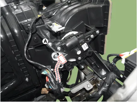
28.Loosen the heater & blower unit mounting bolt (A).
29.Remove the heater and blower unit from the crash pad after loosening the mounting nuts.
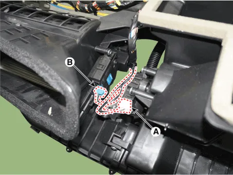
30.Separate the blower unit (A) from the heater unit (B) after loosening the screws.

31.To install, reverse the removal procedure.
Blower Motor
1.Connect the battery voltage and check the blower motor rotation.
2.If the blower motor does not operate well, substitute with a known-good blower motor and check for proper operation.
3.Replace the blower motor if it is proved that there is a problem with it.
1.Disconnect the negative (-) battery terminal.
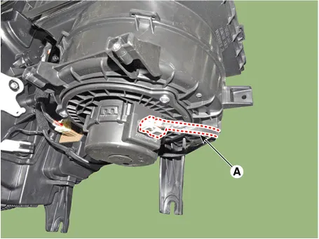
2.Disconnect the blower motor connector (A) and then remove the blower motor (B) after loosening the screws.
3.To install, reverse the removal procedure.
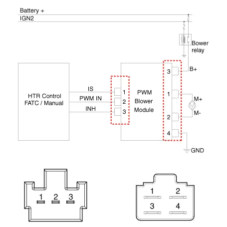
PWM Blower Module
1.Turn the ignition switch ON.
2.Manually operate the control switch and measure the voltage of the blower motor.
3.Select the control switch to raise voltage until the speed gets high.
| Blower Speed | Manual Voltage (V) |
| 1 | 4 |
| 2 | 5.5 |
| 3 | 6.9 |
| 4 | 8.4 |
| 5 | 9.8 |
| 6 | 11.3 |
| 7 | B(+) |
| Blower Speed | Voltage (V) | ||
| Manual Voltage (V) | Auto Voltage (V) | ||
| A/C ON | A/C OFF | ||
| 1 | 3.8 | 3.4 | Auto Low(4.6V) |
| 2 | 4.6 | 4.6 | 4.6 - 5.6 |
| 3 | 5.9 | 5.9 | 5.6 - 6.7 |
| 4 | 7.2 | 7.2 | 6.7 - 7.7 |
| 5 | 8.3 | 8.3 | 7.7 - 8.9 |
| 6 | 9.5 | 9.5 | 8.9 - 10.1 |
| 7 | 11.3 | 11.3 | 10.1 - AUTO HI (10.8V) |
| 8 | B(+) | B(+) |   |
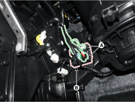
1.Disconnect the negative (-) battery terminal.
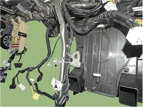
2.Disconnect the connector (A) and then remove the PWM Blower module (B) after loosening the mounting screws.
3.Install in the reverse order or removal.
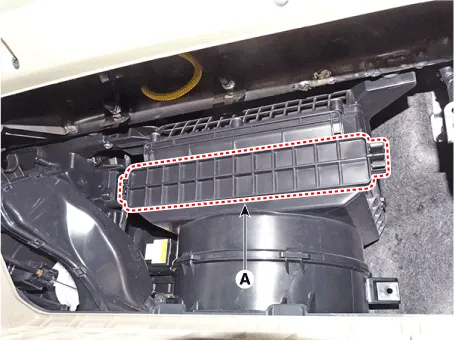
Climate Control Air Filter
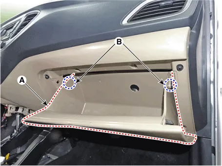
1.Open the glove box (A) in the direction of the arrow.

2.Press both sides of the stoppers (B) down the glove box (A).
3.Remove the filter cover (A) by pressing the knob.
4.Replace the air filter (A) with a new one according to the direction of air filter.
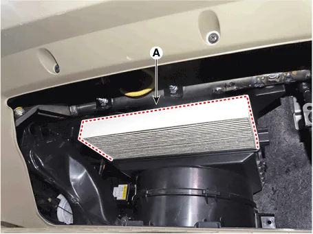

• To remove the filter easily, press the right side inward then pull out the filter.
• In case of driving in an air-polluted area or rugged terrain, check and replace the air filter as frequently as possible.
5.To install, reverse the removal procedure.
Intake Actuator
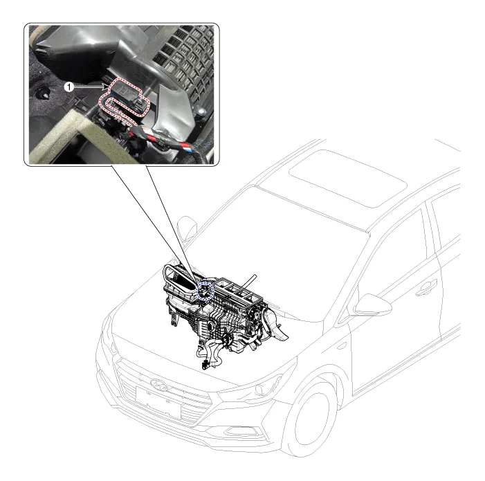
1. Intake actuator
| Door position | Voltage (V) | Error detecting |
| Fresh | 0.3 ± 0.15 | Low voltage : 0.1V or less |
| Recycle | 4.7 ± 0.15 | High voltage : 4.9V or more |
1.Turn the ignition switch OFF.
2.Disconnect the intake actuator connector.
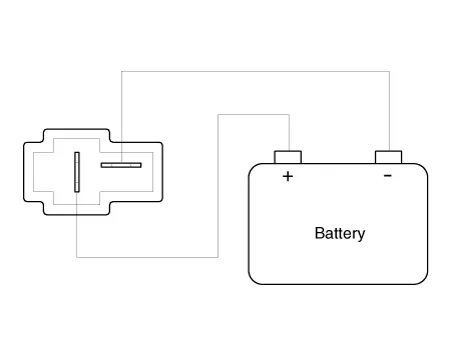
3.Verify that the intake actuator operates to the fresh position when connecting 12V to terminal 6 and grounding terminal 5.Verify that the intake actuator operates to the recirculation position when connected in reverse.
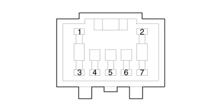
| Pin NO | Function |
| 1 | - |
| 2 | - |
| 3 | Fresh air |
| 4 | Sensor (+5V) |
| 5 | Feedback signal |
| 6 | Sensor ground |
| 7 | Recirculated air |
4.Connect the intake actuator connector.
5.Turn the ignition switch ON.
6.Check the voltage between terminal 6 and 5.
7.If the measured voltage is not within specification, check the operation by replacing the existing intake actuator with a new genuine part. After that, determine whether replacement of the temperature control actuator is required or not.
1.The heating, ventilation and air conditioning can be quickly diagnosed failed parts with vehicle diagnostic system (GDS).※ The diagnostic system (GDS) provides the following information.(1) Self diagnosis : Checking the failure code (DTC) and display.(2) Current data : Checking the system input / output data state.(3) Actuation test : Checking the system operation condition.(4) Additional function : Other controlling such as he system option and zero point adjustment.
2.Select the 'Car model' and the system to be checked in order to check the vehicle with the tester.
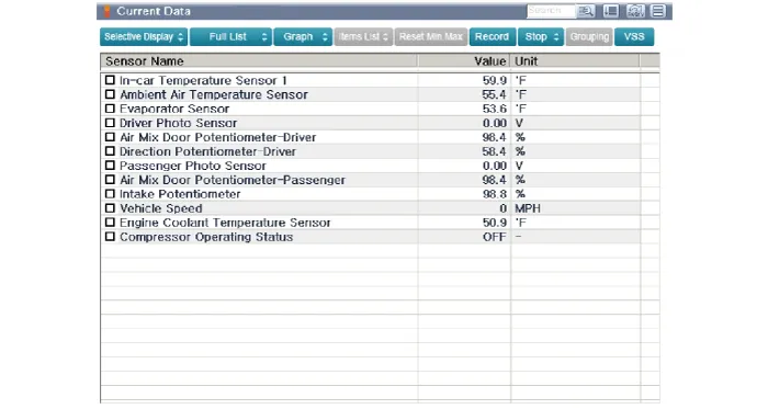
3.Select the 'Current data' menu to search the current state of the input / output data.The input / output data for the sensors corresponding to the Intake Actuator can be checked.
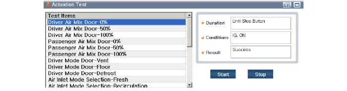
4.To perform compulsory operation on Intake Actuator input factors, select "ACTUATION TEST".
1.Disconnect the negative (-) battery terminal.
2.Remove the main crash pad assembly.(Refer to Body - "Main Crash Pad Assembly")
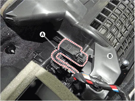
3.Disconnect the connector (A) and then remove the intake actuator (B) after loosening the mounting screws.
4.To install, reverse the removal procedure.


Other information:
Hyundai Accent (HC) (2017 - 2022) Service Manual: Storage compartment
Use the storage compartments in your Hyundai Accent to keep everyday items organized and secure, and always stow loose objects before driving. WARNING Never store cigarette lighters, propane cylinders, or other flammable/explosive materials in the vehicle. These items may catch fire and/or explode if the vehicle is exposed to hot temperatures for extended periods.Information - Using Bluetooth® Wireless Technology(BT) Cellular Phone Bluetooth® Wireless Technology is a near-field wireless networking technology that uses the 2.4 GHz frequency to connect various devices within a certain distance wirelessly. In the Hyundai Accent, Bluetooth® Wireless Technology supports handsfree calling and (when compatible) media streaming.
Contents
Categories
- Manuals Home
- Hyundai Accent Owners Manual
- Hyundai Accent Service Manual
- Questions & Answers
- Video Guides
- Useful Resources
- New on site
- Most important about car
- Privacy Policy

0.0104