Hyundai Accent (HC): Heating, Ventilation and Air Conditioning / Controller
Contents:
Heater & A/C Control Unit (Manual)
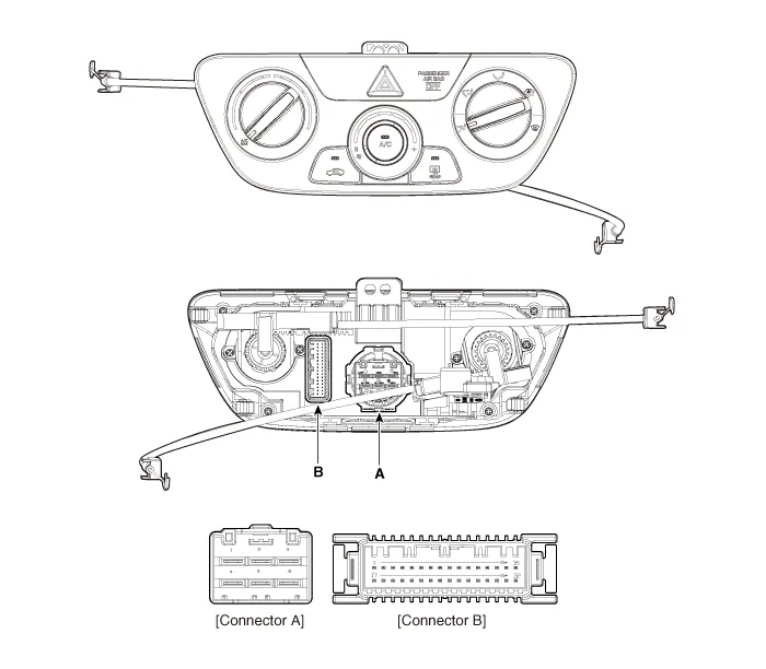
| Connector | Pin NO | Function | Connector | Pin NO | Function |
| B | 1 | Battery (+) | B | 17 | IGN2 |
| 2 | - | 18 | ILL+ (TAIL) | ||
| 3 | IGN1 | 19 | - | ||
| 4 | - | 20 | Sensor ground REF (+5V) | ||
| 5 | Intake actuator (Fresh) | 21 | HTD (Rear defog indicator) | ||
| 6 | Intake actuator (Recirculation) | 22 | Hazard signal | ||
| 7 | Intake actuator (Feedback) | 23 | Rear defog swich | ||
| 8 | Evaporator Temperature Sensor (+) | 24 | - | ||
| 9 | Ambient Temperature Sensor (+) | 25 | - | ||
| 10 | Blower on signal common | 26 | - | ||
| 11 | Max blower on signal | 27 | |||
| 12 | - | 28 | ECV+ | ||
| 13 | C_CAN High | 29 | ECV- (Ground) | ||
| 14 | C_CAN Low | 30 | ILL- (RHEO) | ||
| 15 | - | 31 | Sensor ground | ||
| 16 | Ground | 32 | Ground |
1.Disconnect the negative (-) battery terminal.
2.Remove the crash pad lower panel.(Refer to Body - "Crash Pad Lower Panel")
3.Remove the audio unit.(Refer to Body Electrical System - "Audio Unit")
4.Remove the glove box.(Refer to Crash Pad - "Glove Box Upper Cover Housing")
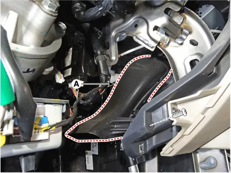
5.Remove the driver's side shower duct (A) after loosening the screw.
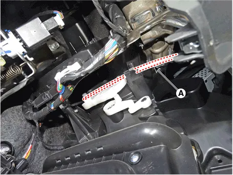
6.Disconnect the mode control cable (A).
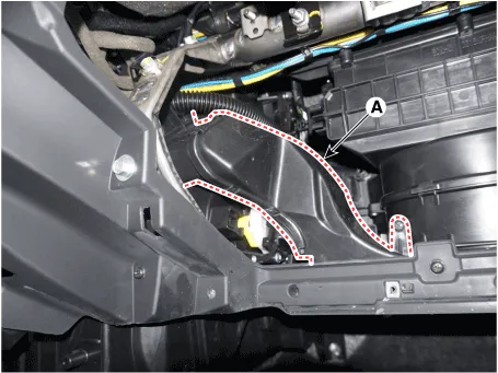
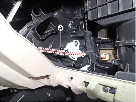
7.Remove the passenger's side shower duct (A) after loosening the screw.
8.Disconnect the temperature control cable (A).
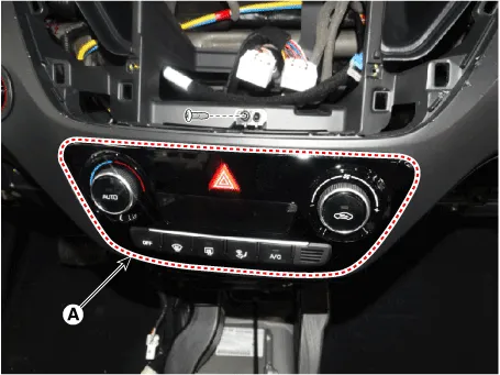
9.After loosening the mounting screws, remove the A/C & heater controller unit (A).
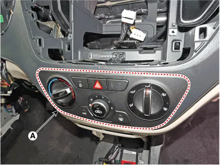
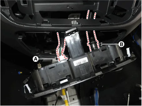
10.Disconnect the A/C & heater controller connectors (A).
11.To install, reverse the removal procedure.
Heater & A/C Control Unit (FATC)
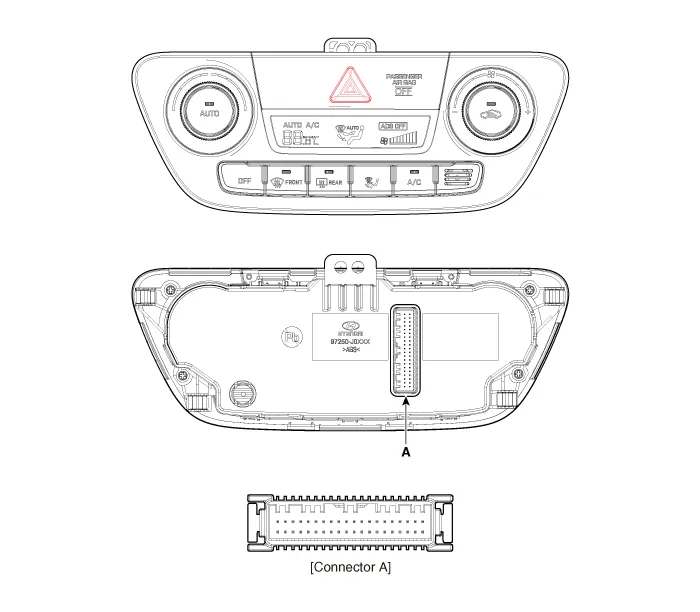
| Connector | Pin NO | Function | Connector | Pin NO | Function |
| A | 1 | Battery (+) | A | 21 | IGN2 |
| 2 | ADS Sensor (PWM) | 22 | IGN1 | ||
| 3 | ILL+ (TAIL) | 23 | HTD (Rear defog indicator) | ||
| 4 | C_CAN High | 24 | PAB off signal | ||
| 5 | C_CAN Low | 25 | PAB IGN1 | ||
| 6 | Defrost actuator (Open) | 26 | Sensor ground REF (+5V) | ||
| 7 | Defrost actuator (Close) | 27 | Detent out (-) | ||
| 8 | Mode control actuator (Vent) | 28 | Ambient Temperature Sensor (+) | ||
| 9 | Mode control actuator (Def) | 29 | Evaporator Temperature Sensor (+) | ||
| 10 | Temperature control actuator (Cool) | 30 | Photo sensor (-) | ||
| 11 | Temperature control actuator (Warm) | 31 | - | ||
| 12 | Intake actuator (Fresh) | 32 | - | ||
| 13 | Intake actuator (Recirculation) | 33 | Hazard signal | ||
| 14 | Mode control actuator (Feedback) | 34 | Rear defog swich | ||
| 15 | Tmperature control actuator (Feedback) | 35 | - | ||
| 16 | Intake actuator (Feedback) | 36 | Blower motor (+) | ||
| 17 | Defrost actuator (Feedback) | 37 | Fet (Drain feedback) | ||
| 18 | ECV+ | 38 | Fet (Gate) | ||
| 19 | ECV- (Ground) | 39 | Sensor ground | ||
| 20 | ILL- (RHEO) | 40 | Ground |
1.Self-diagnosis process.
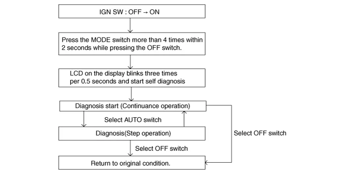

• When operating the self-diagnostics, the below fault (self-diagnostics code) will blink at 0.5 seconds interval on the temperature display settings (driver's side only) and the remaining symbols are OFF .
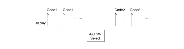
2.Fault code display
(1)Continuance operation : DTC code.

(2)Continuance operation : DTC code.

(3)STEP operation.A. Nomal or one fault code is same as a continuance operation. B. DTC code.
3.If fault codes are displayed during the check, Inspect malfunction causes by referring to fault codes.
| Display | Fail description | Note |
| 0 | Normal | |
| 11 | Incar sensor OPEN | |
| 12 | Incar sensor SHORT | |
| 13 | Ambient sensor OPEN | |
| 14 | Ambient sensor SHORT | |
| 17 | Evaporator sensor OPEN | |
| 18 | Evaporator sensor SHORT | |
| 19 | Driver temp door potentionmeter OPEN or SHORT | |
| 20 | Driver temp door potentionmeter Error | |
| 21 | Mode door potentionmeter OPEN or SHORT | |
| 22 | Mode door potentionmeter Error | |
| 23 | Auto defog sensor OPEN | |
| 24 | Auto defog sensor SHORT | |
| 25 | Intake door potentionmeter OPEN or SHORT | |
| 26 | Intake door potentionmeter Error | |
| 43 | Defog door potentiometer OPEN or SHORT | |
| 44 | Defog door potentiometer Error | |
| 45 | APT CAN Signal Error | |
| 47 | RPM CAN Signal Error | |
| 48 | Vehicle speed CAN Signal Error | |
| 49 | Engine coolant temprature CAN Signal Error | |
| 50 | Cluster ionizer fault | |
| 71 | ECV Fault (OPEN) | |
| 85 | Blower motor Error | North America Type ONLY |
4.Fail safe
| NO | Item | Fault | Fail Safe |
| 1 | Amblent sensor | Open or Short | Control with the value of 20°C(67°F) |
| 2 | Incar sensor | Open or Short | Control with the value of 25°C(77.0°F) |
| 3 | Evaporator sensor | Open or Short | Control with the value of -2°C(28.4°F) |
| 4 | Temperature control actuator | Open or Short | If temperature setting 17°C(62.6°F) - 24.5°C(76.1°F), fix at maximum cooling position. If temperature setting 25°C(77°F) - 32°C(89.6°F), fix at maximum heating position. |
| 5 | Mode control actuator | Open or Short | Fix vent position, while selecting vent mode. Fix recirculation position, while selecting recirculation mode. |
| 6 | Intake control actuator | Open or Short | Fix fresh position, while selecting fresh mode. Fix recirculation position, while selecting recirculation mode. |
| 7 | Defogging door potentiometer | Open or Short | In the VENT, Bi-Level mode, DEF Door Potention Meter is fixed in CLOSE position. In the mode other VENT, Bi-Level mode, DEF Door Potention Meter is fixed in OPEN position. |
| 8 | Auto defogging sensor | Open or Short | Control with the value of 0% |
| 9 | ECV | Open | CF_Fatc_EcvFlt = 01H (fault) ECV OFF, A/C Output OFF, 0Nm |
| 10 | VS (Vehicle Speed) | FFh or NO reception | VS-TCU (From TCU2) |
| 11 | VS TCU (Vehicle Speed Calculated by TCU) | FFh or NO reception | VS-TCU (From TCU2) |
| 12 | N (Engine speed) | NO reception | Control with the value of 650rpm |
| 13 | F_N_ENG | 0.1h or NO reception | Control with the value of 650rpm |
| 14 | TPS (Throttle position signal) | FFh or NO reception | Control with the value of 0% |
| 15 | TEMP_ENG | FFh or NO reception | Control with the value of 25°C(194.0°F) |
| 16 | R_TqAcnApvC | FFh or NO reception | Control with the value of 0Nm |
| 17 | R _ PAcnC (APT Sensor Output Value) | FFh or NO reception | Control with the value of 0 hPa (ECV OFF) |
| 18 | RLY-AC (Activation of air conditioner compressor relay) | NO reception | Control with the value of 0 hPa (ECV OFF) |
| 19 | R _ NEngIdlTgC (Engine Idle Target Speed) | FFh or NO reception | Control with the value of 0 hPa (ECV OFF) |
| 20 | SOAK_TIME (Engine Soaking Time) | NO reception | Control with the value of IGN off Time |
| 21 | SOAK_TIME_ERROR (Soak Time Error) | 0.1h or NO reception | Control with the value of IGN off Time |
| 22 | Sunroof ON/OFF (CF_SunRoofOpenstate) | CAN signal | CF_SunRoofOpenState=OH |
1.Disconnect the negative (-) battery terminal.
2.Remove the glove box upper cover housing.(Refer to Body - "Glove Box Upper Cover Housing")
3.Remove the audio unit.(Refer to Body Electrical System - "Audio Unit")
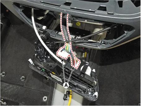
4.After loosening the mounting screws, remove the A/C & heater controller unit (A).
5.Disconnect the A/C & heater controller connector (A) and hose (B).
6.To install, reverse the removal procedure.


Other information:
Hyundai Accent (HC) (2017 - 2022) Service Manual: Emission control system
The emission control system on your Hyundai Accent is covered by a written limited warranty. Review the warranty details in the Owner’s Handbook & Warranty Information booklet supplied with the vehicle. Your Hyundai Accent is equipped with an emission control system designed to meet applicable emissions regulations. The system is made up of three main parts, as follows.Hyundai Accent (HC) (2017 - 2022) Service Manual: Stop Lamp Switch
- Components 1. Brake pedal member assembly2. Stop lamp switch3. Brake pedal arm 4. Pedal pad - Schematic Diagram - System circuit diagram - Terminal function TerminalDescription 1IGN 2BS 3- 4B+ 5BLS 6GND - Adjustment 1.Turn ignition switch OFF and disconnect the negative (-) battery cable. 2.Remove the lower crash pad.
Contents
Categories
- Manuals Home
- Hyundai Accent Owners Manual
- Hyundai Accent Service Manual
- Questions & Answers
- Video Guides
- Useful Resources
- New on site
- Most important about car
- Privacy Policy

0.0063