Hyundai Accent (HC): Brake System / Stop Lamp Switch
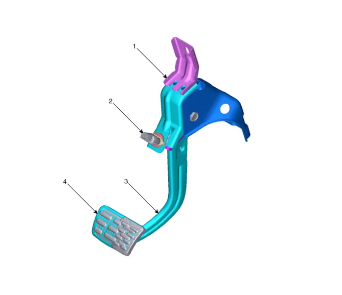
1. Brake pedal member assembly
2. Stop lamp switch
3. Brake pedal arm
4. Pedal pad

| Terminal | Description |
| 1 | IGN |
| 2 | BS |
| 3 | - |
| 4 | B+ |
| 5 | BLS |
| 6 | GND |
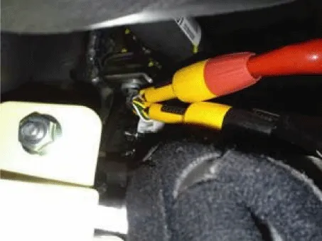
1.Turn ignition switch OFF and disconnect the negative (-) battery cable.
2.Remove the lower crash pad.(Refer to Body - "Crash Pad")
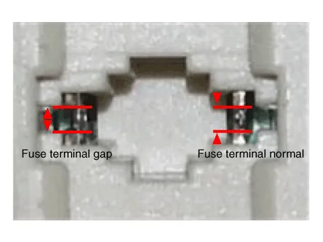
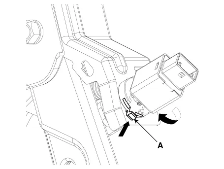
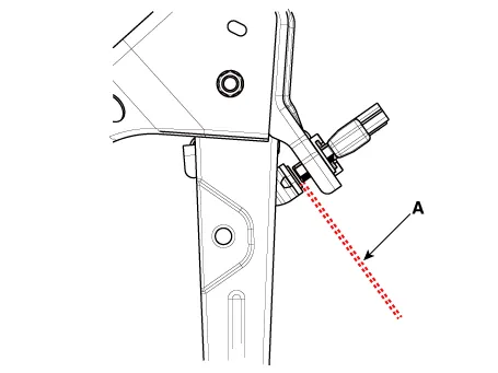
3.Confirm the gap between stop lamp switch and bracket.
Stop lamp clearance (A) : 1.0 - 2.0 mm (0.04 - 0.08 in.)

4.If the gap between stop lamp switch and bracket is not 1.0-2.0mm (0.04-0.08in), check the mounting clip and other part of around stop lamp.
5.If there is normal, remove the stop lamp switch and then install again.
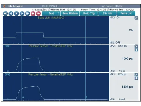
1.Analyze GDS data and confirm if there is anything wrong with the stop lamp switch.
(1) Connect the GDS to the self-diagnosis connector.
(2) Turn the spark switch on
(3) Step on the brake pedal.
(4)Inspect the "brake switch" category that displays the "sensor data" GDS.)
Normal waveform : The pressure sensor signal value will change according to the brake ON/OFF switch.
1.Turn ignition switch OFF and disconnect the negative (-) battery cable.
2.Remove the lower crash pad.(Refer to Body - "Crash Pad")
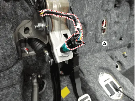
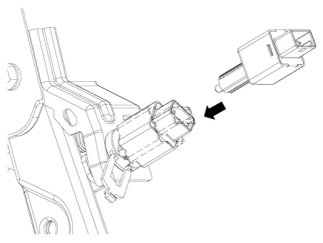
3.Disconnect the stop lamp switch connector (A).
4.Pull the locking plate (A) as indicated by the arrow.
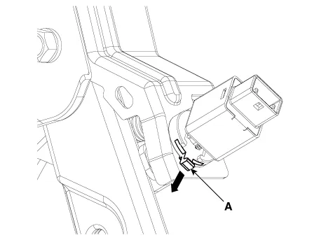
5.Turn brake switch 45° counterclockwise and remove it.
6.Check the stop lamp switch.
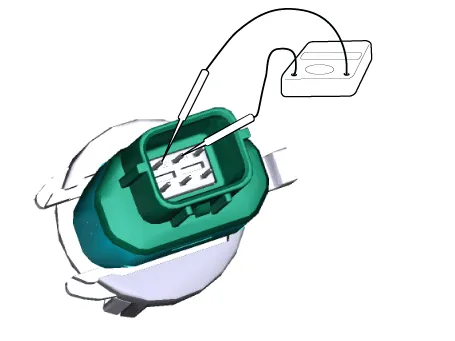
(1) Connect a circuit tester to the connector of stop lamp switch, and check whether or not there is continuity when the plunger of the stop lamp switch is pushed in and when it is released.
(2)The stop lamp switch is in good condition if there is no continuity when plunger is pushed.
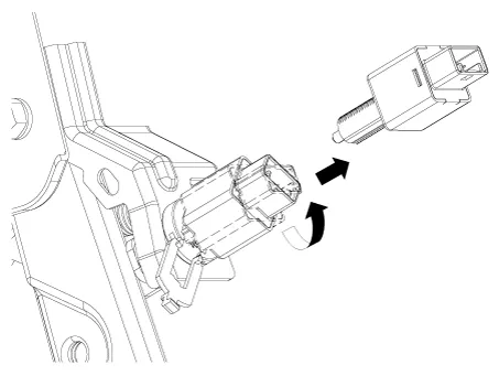
1.Fix the brake pedal arm and insert fully the brake switch so that the contact part is invisible.
2.After inserting, turn the brake switch 45° clockwise, and then assemble locking plate (A) by pushing.
3.Confirm the gap between stop lamp switch and bracket.
Stop lamp clearance : 1.0 - 2.0 mm (0.04 - 0.08 in.)

• If the gap between stop lamp switch and bracket is not 1.0-2.0mm (0.04-0.08in), perform the above process again.
4.Connect the brake lamp switch connector (A).

5.Install the lower crash pad.(Refer to Body - "Crash Pad")
6.Connect the negative (-) battery cable.
1. Part diagnosis
| Items | Cause | Symptom | ||||||||||
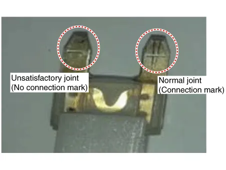
| Switch fuse | Faulty fuse connection, Damaged fuse |
| â‘
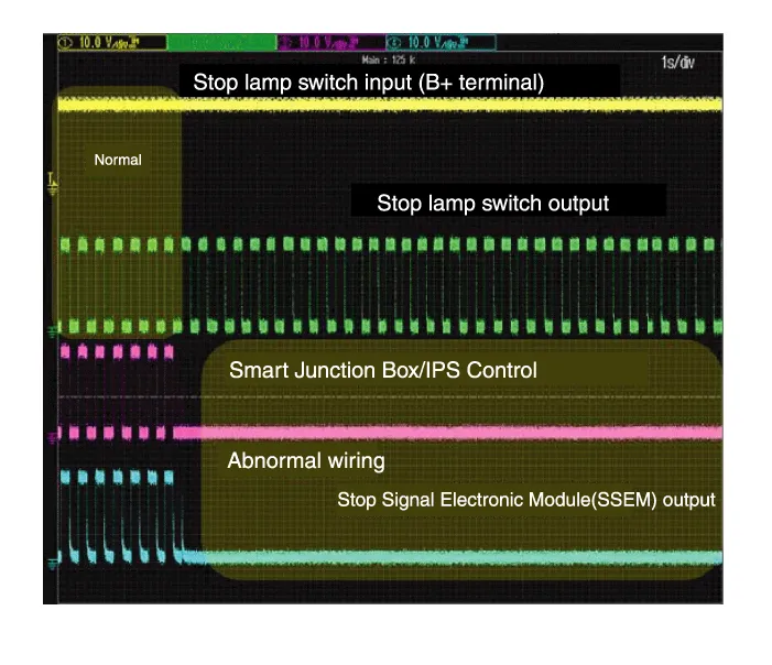
A waveform inspection is performed using an oscilloscope on each part
during vehicle acceleration/braking. (Refer to stop lamp switch circuit
inspection procedures) ② Refer to the relevant repair procedures of the part when something abnormal is discovered in the waveform (Refer to the repair procedures of the relevant part and if necessary replace it) | |||||||||
| Relay fuse | Faulty fuse connection, Damaged fuse |
| ||||||||||
| Stop lamp switch |
|
| ||||||||||
| Stop signal electronic module (If it applies) |
| |||||||||||
| Engine control module (ECM) |
| |||||||||||
| Body control module (BCM) |
| |||||||||||
| Shift-lock solenoid |
| |||||||||||
| Inhibitor switch |
| |||||||||||
| Smart Key Unit (SMK) |
| |||||||||||
| Electronic parking brake |
| |||||||||||
| ABS/VDC control module (Pressure sensor) |
|
2. Symptom diagnosis
| Symptom | Part that could be the cause | |
| Trouble starting | Switch fuse, Relay fuse, Stop lamp switch, Stop signal electronic module, ABS/VDC control module, Each wire, Connector | â‘
Inspect waveform using an oscilloscope on each part during vehicle
acceleration/braking. (Refer to stop lamp switch circuit inspection
Procedures) ② Refer to the relevant repair procedures of the part when something abnormal is discovered in the waveform (Refer to the repair procedures of the relevant part and if necessary replace it) |
| Trouble shifting gears | Switch fuse, Relay fuse, Stop lamp switch, Stop signal electronic module, BCM, ECM, Inhibitor switch, Each wire, Connector | |
| ESP OFF light illuminated | Switch fuse, Relay fuse, Stop lamp switch, Stop signal electronic module, ABS/VDC control module, Each wire, Connector | |
| P0504 | Switch fuse, Relay fuse, Stop lamp switch, Stop signal electronic module, ECM, Each wire, Connector | |
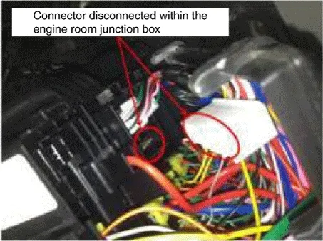
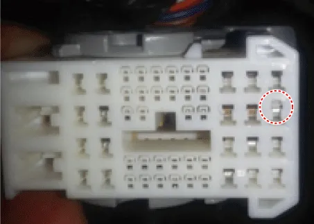
| Stop lamp does notworking | Switch fuse, Relay fuse, Stop lamp switch, Stop signal electronic module, Wire/Connector disconnected | |
| Stop lamp always turns on | Stop lamp switch, Stop signal electronic module, Wiring short circuit, Damaged fuse |
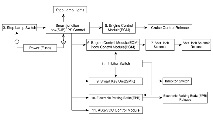
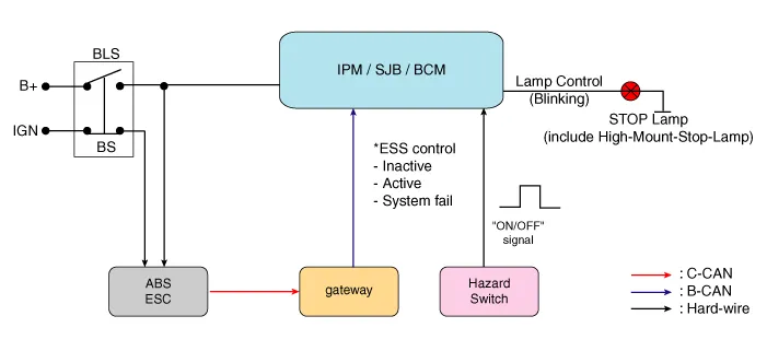
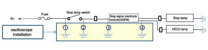
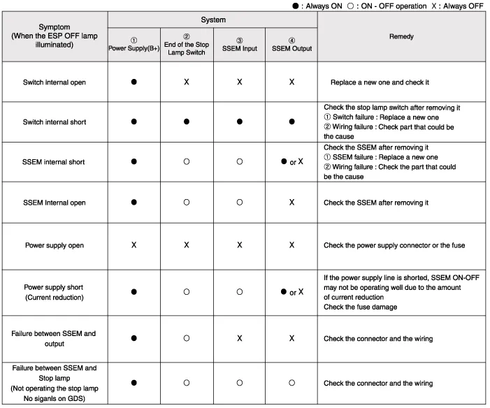
3.Stop lamp switch system diagnosis
4.Refer to DTC guide when the related DTC codes are displayed.


Other information:
Hyundai Accent (HC) (2017 - 2022) Service Manual: Repair procedures
- Diagnosis with Diagnostic tool 1.In the body electrical system, failure can be quickly diagnosed by using the vehicle diagnostic system (Diagnostic tool).The diagnostic system (Diagnostic tool) provides the following information.(1)Fault Code Searching : Checking failure and code number (DTC) (2)Data Analysis : Checking the system input/output data state (3)Actuation test : Checking the system operation condition (4)S/W Management : Controlling other features including system option setting and zero point adjustment Data Analysis 1.Hyundai Accent (HC) (2017 - 2022) Service Manual: Cylinder Head
- Removal • Use Fender cover to avoid damaging painted surfaces. • To avoid damaging the cylinder head, wait until the engine coolant temperature drops below normal temperature before removing it. • When handling a metal gasket, take care not to fold the gasket or damage the contact surface of the gasket. • To avoid damage, unplug the wiring connectors carefully while holding the connector portion.
Categories
- Manuals Home
- Hyundai Accent Owners Manual
- Hyundai Accent Service Manual
- Questions & Answers
- Video Guides
- Useful Resources
- New on site
- Most important about car
- Privacy Policy

0.0082