Hyundai Accent (HC): Manual Transaxle System (M6CF1) / Manual Transaxle Control System
Contents:
Shift Lever
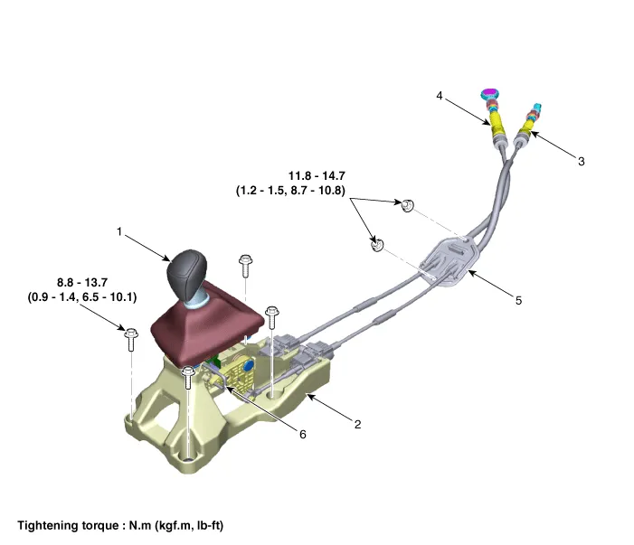
1. Shift lever knob & boots
2. Shift lever assembly
3. Select cable
4. Shift cable
5. Retainer
6. 4th fixing pin
1.Turn OFF ignition switch and disconnect the negative (-) battery cable.
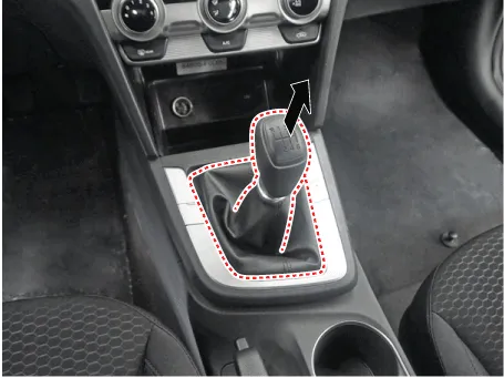
2. Remove the shift lever knob & boots (A) pull both of it up.
3.Remove the floor console assembly. (Refer to Body - "Floor Console")
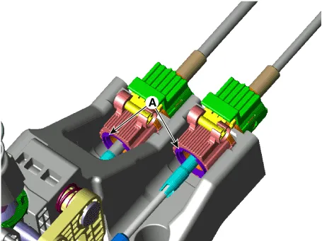
4.Separate the select cable (B), after removing the snap pin (A).
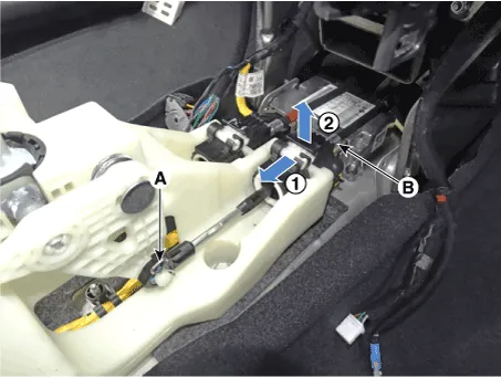
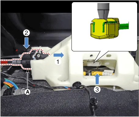
5. Remove the shift cable.
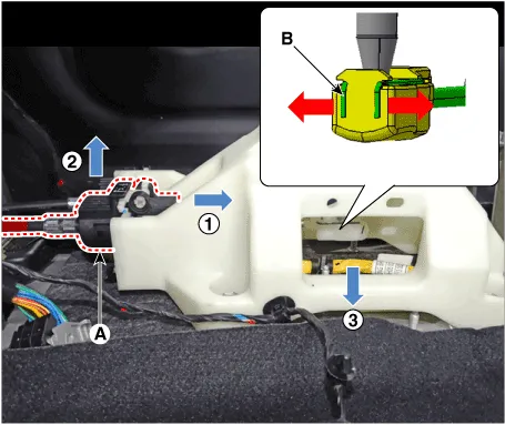
(1)Remove the cable socket (A), after release the lock.
(2)Remove the clip, in the shape of a "U"(B), from the cable end by spreading it towards both sides.

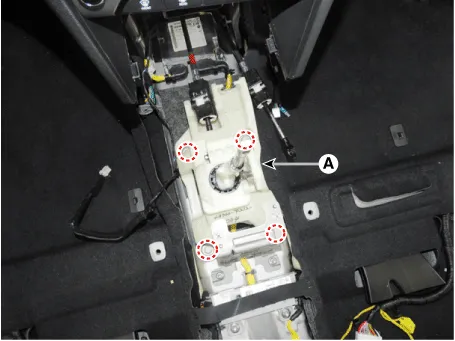
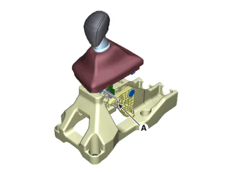
6.Loosen the bolts and then removing the shift lever (A).
Tightening torque :8.8 - 13.7 N.m (0.9 - 1.4 kgf.m, 6.5 - 10.1 lb-ft)
1.To install, reverse the removal procedures.

• New shift lever assembly is mounted in the 4th fixing pin.After installation, remove the 4th fixed pin.
• After installing the select cable and shift cable socket, check portion (A) to see if it projects outwards from the cap.

• Check operating of lever of transaxle side when operating shift lever after assembly. (1~6,R)
• If there is sticky feel, adjust the control cable length again.(Refer to Control Cable - "Installation")
Control Cable

1. Shift lever knob & boots
2. Shift lever assembly
3. Select cable
4. Shift cable
5. Retainer
6. 4th fixing pin
1.Move the shift lever to 4th gear.
2.Turn OFF ignition switch and disconnect the negative (-) battery cable.
3.Remove the air cleaner assembly and air duct.(Refer to Engine Mechanical System - "Air Cleaner")
4.Remove the battery and battery tray.(Refer to Engine Electrical System - "Battery")
5.Remove the Engine Control Module (ECM).(Refer to Engine Control System - "ECM")
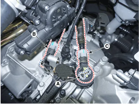
6.Separate the control cable.
1)Remove the snap pin (A).
2)Separate the select cable (B) and then shift cable (C).

7.Remove the shift knob & boot (A).

8.Remove the floor console assembly. (Refer to Body - "Floor Console")
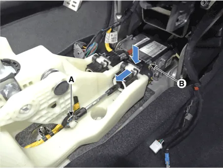
9.Separate the select cable (B), after removing the snap pin (A).

10.Remove the shift cable.
(1)Remove the cable socket (A), after release the lock.
(2)Remove the clip, in the shape of a "U"(B), from the cable end by spreading it towards both sides.
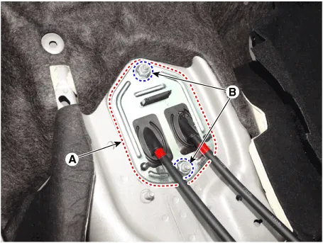
11.Loosen the nuts and then removing the retainer (A).

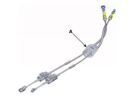
12.Remove the control cable assembly (A) from the vehicle.

• Place the shift lever and transaxle side lever in 4th shift position and insert the lever fixing pin (A).

1.Install the retainer (A) and then tighten the nuts (B).
Tightening torque :11.8 - 14.7 N.m (1.2 - 1.5 kgf.m, 8.7 - 10.8 lb-ft)
2. Install the select cable (B), and then fixing the snap pin (A).
3.Install the shift cable (A).

• After installing the select cable and shift cable socket, check portion (A) to see if it projects outwards from the cap.
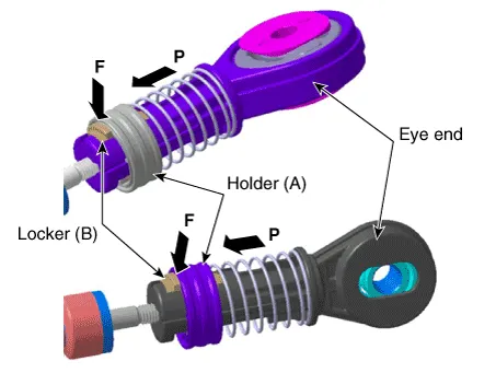
4.Move the locker (B) in the direction of "F" with pulling the holder (A) in the direction of "P".

5. Install the control cable.
1)Install the snap pin (A).
2) Separate the select cable (B) and then shift cable (C).

6.Tighten the holder (A) to the "P" directions after fixing the rockers (B) in the "F" direction.
7.Remove the shift lever 4th fixed pin (A).
8.Install the floor console assembly.(Refer to Body - "Floor Console")
9.Install the battery and battery tray.(Refer to Engine Electrical System - "Battery")
10.Install the engine control module (ECM).(Refer to Engine Control System - "ECM")
11. Install the air cleaner assembly and air duct.(Refer to Engine Mechanical System - "Air Cleaner")

• Check operating of lever of transaxle side when operating shift lever after assembly. (1~6,R)
• If there is sticky feel, adjust the control cable length again.(Refer to Control Cable - "Installation")
Control Shaft Complete
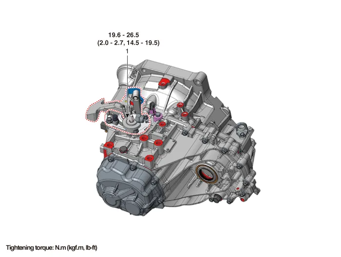
1. Control shaft complete
1.Set shift lever to N position.
2.Turn OFF ignition switch and disconnect the negative (-) battery cable.
3.Remove the air cleaner assembly and air duct.(Refer to Engine Mechanical System - "Air Cleaner")
4.Remove the battery and battery tray.(Refer to Engine Electrical System - "Battery")
5.Remove the engine control module (ECM).(Refer to Engine Control System - "ECM")
6.Separate the control cable.
1)Remove the snap pin (A).
2)Separate the select cable (B) and then shift cable (C).
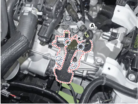
7.Remove the control shaft assembly (A) after loosening the bolts.
Tightening torque :19.6 - 26.5 N.m (2.0 - 2.7 kgf.m,14.5 - 19.5 lb-ft)
1.To install, reverse the removal procedures.

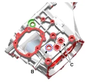
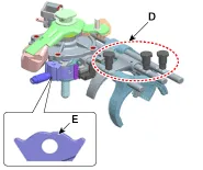
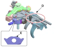
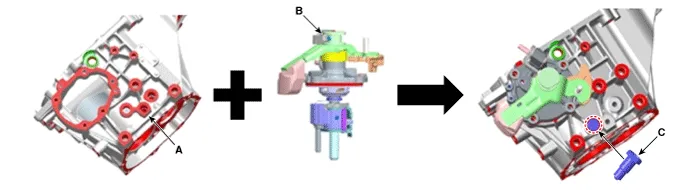
1)Main changes of the M/T case- A : 3 poppet ball taps- B : 1 poppet ball tap for 5th/6th shift rail- C : 2 poppet ball taps for (1st/2nd, 3rd/4th) shift rails have been deleted.- D : The number of poppet balls has been reduced from 3EA to 1EA and the grooves on the 1st/2nd, 3rd/4th shift rails have been deleted.- E : The shift groove of control finger has been changed in shape.
| M/T type | Previous | New |
| Case |
|
|
| Control Shaft Complete |
|
|
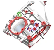
2)When trying to replace the previously designed control shaft complete with a newly designed one from the previously designed M/T case. - Replace with a newly designed control shaft complete (A), Remove the poppet ball (C-2ea) for 1st/2nd, 3rd/4th shift rails from the previously designed M/T case (B) and then assemble the seal bolt (D-2ea) to that position.
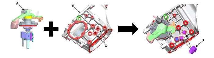
3)When trying to replace the previously designed M/T case with a newly designed one. - Be sure to also replace the previously designed control shaft complete (B) with A newly designed one as well as the M/ T case (A).- Assemble poppet bolt (C-1ea) to the newly designed M/T case (A) (Previous: 3ea).
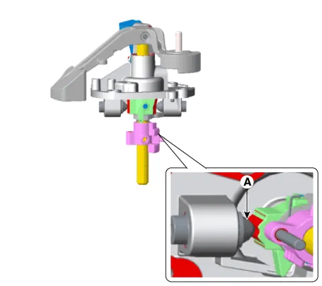
• When installing, set control shaft lever to neutral position (A).
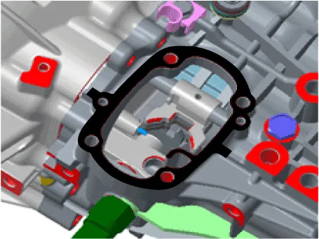
• Apply the sealant to the contact surface of transaxle and control shaft.
Specified sealant : LOCTITE 5060
2.After installing, check to be sure that this part operates as designed at each range of transaxle side corresponding to each position of shift lever.


Other information:
Hyundai Accent (HC) (2017 - 2022) Service Manual: Description and Operation
- Description The SMART KEY system is a system that allows the user to access and operate a vehicle in a very convenient way. To access the vehicle, no traditional key or remote control unit is needed.The user carries a SMART KEY FOB which does not require any conscious actions by the user (e.g. operate a RKE button). The SMART KEY system is triggered by pressing a push button in the door handle.
Contents
Categories
- Manuals Home
- Hyundai Accent Owners Manual
- Hyundai Accent Service Manual
- Questions & Answers
- Video Guides
- Useful Resources
- New on site
- Most important about car
- Privacy Policy

0.0082