Hyundai Accent (HC): Engine Mechanical System / Cylinder Head Assembly
Contents:
Components and Components Location
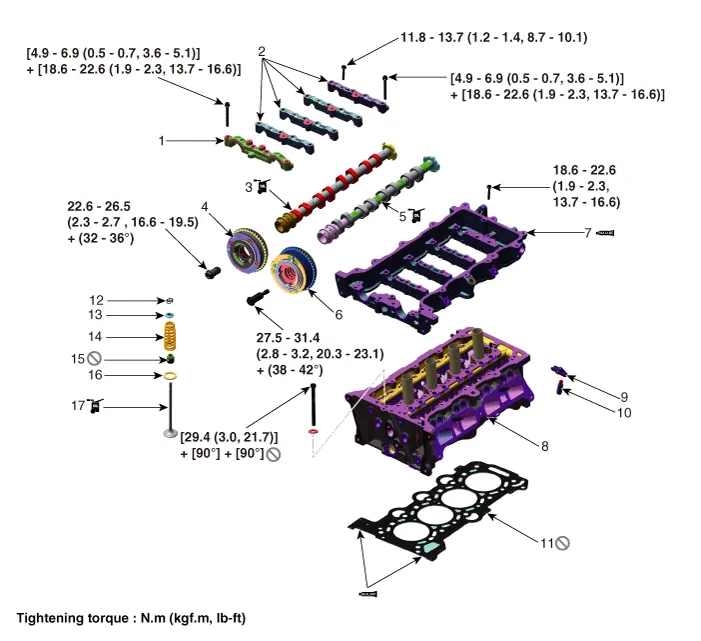
1. Camshaft front bearing cap
2. Camshaft bearing cap
3. Exhaust camshaft
4. Exhaust CVVT assembly
5. Intake camshaft
6. Intake CVVT assembly
7. Cam carrier
8. Cylinder head
9. Swing arm
10. Hydraulic lash adjuster (HLA)
11. Cylinder head gasket
12. Retainer lock
13. Retainer
14. Valve spring
15. Valve stem seal
16. Valve spring seat
17. Valve
Cylinder Head Cover
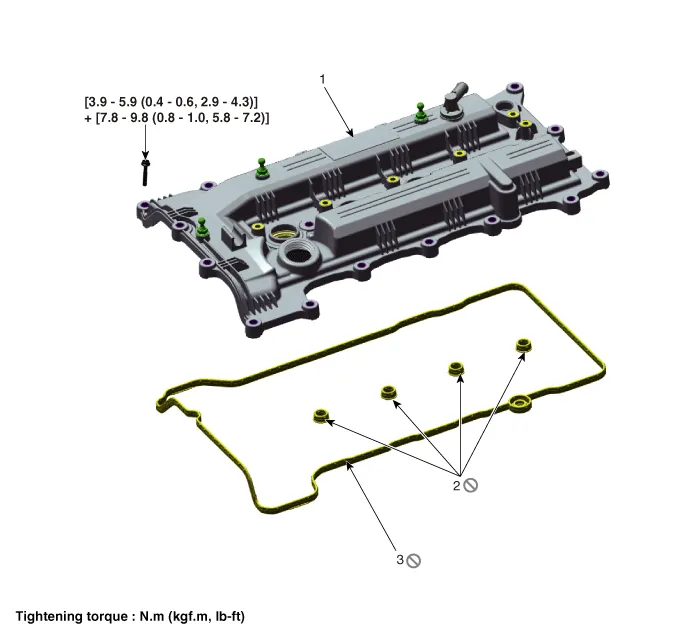
1. Cylinder head cover
2. Cylider head cover gasket (Inner)
3. Cylider head cover gasket (Outer)
1.Disconnect the battery negative terminal.
2.Remove the engine cover.(Refer to Engine And Transaxle Assembly - "Engine Cover")
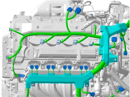
3.Disconnect the wiring connectors and harness clamps and remove the connector brackets around the cylinder head cover.
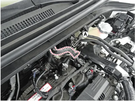
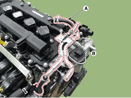
4.Disconnect the brake vacuum hose (A).
5.Disconnect the breather hose A (A) and than remove the vacuum pipe mounting bolts (B).
Tightening torque : 9.8 - 11.8 N.m (1.0 - 1.2 kgf.m, 7.2 - 8.7 lb-ft)
6.Remove the ignition coils. (Refer to Engine Electrical System - "Ignition Coil")
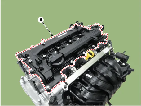
7.Remove the cylinder head cover (A).
8.Remove the cylinder head cover inner gaskets (A) and outer gasket (B).

1.Install the cylinder head cover.
(1)Install the new inner gaskets (A) and outer gasket (B) to the cylinder head cover.
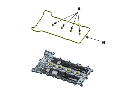

• Always use the new inner and outer cylinder head cover gaskets.
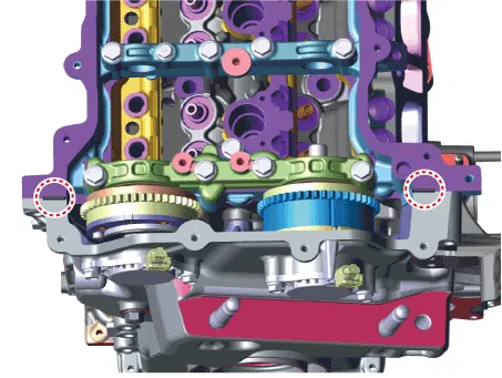
(2)The hardening sealant located on the upper area between timing chain cover and cam carrier should be removed before assembling cylinder head cover.
(3)Apply liquid gasket sealant to the marked area of the cam carrier and assemble within 5 minutes of application.
Width : 2 - 3 mm (0.0787 - 0.1181 in.)Specification : LOCTITE 5900H or above.
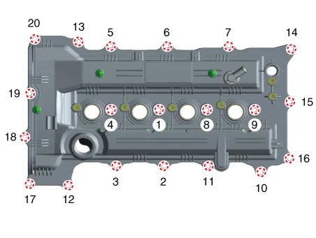
(4)Install the cylinder head cover by tightening the bolts, in several passes, in the sequence as shown.
Tightening torqueStep 1 : 3.9 - 5.9 N.m (0.4 - 0.6 kgf.m, 2.9 - 4.3 lb-ft)Step 2 : 7.8 - 9.8 N.m (0.8 - 1.0 kgf.m, 5.8 - 7.2 lb-ft)


• The firing and/or blow out test should not be performed within 30 minutes of assembling the cylinder head cover.
2.Install the other parts in the reverse order of removal.
CVVT & Camshaft ➤
Cylinder Head ➤


Other information:
Hyundai Accent (HC) (2017 - 2022) Service Manual: Description and Operation
- Description The SMART KEY system is a system that allows the user to access and operate a vehicle in a very convenient way. To access the vehicle, no traditional key or remote control unit is needed.The user carries a SMART KEY FOB which does not require any conscious actions by the user (e.g. operate a RKE button). The SMART KEY system is triggered by pressing a push button in the door handle.Hyundai Accent (HC) (2017 - 2022) Service Manual: Stop Lamp Switch
- Components 1. Brake pedal member assembly2. Stop lamp switch3. Brake pedal arm 4. Pedal pad - Schematic Diagram - System circuit diagram - Terminal function TerminalDescription 1IGN 2BS 3- 4B+ 5BLS 6GND - Adjustment 1.Turn ignition switch OFF and disconnect the negative (-) battery cable. 2.Remove the lower crash pad.
Contents
Categories
- Manuals Home
- Hyundai Accent Owners Manual
- Hyundai Accent Service Manual
- Questions & Answers
- Video Guides
- Useful Resources
- New on site
- Most important about car
- Privacy Policy

0.0071