Hyundai Accent (HC): Engine Mechanical System / Timing System
Contents:
- Components and Components Location
- Drive Belt
- Drive Belt Tensioner
- Crankshaft Damper Pulley
- Front Oil Seal
- Timing Chain Cover
- Timing Chain
Components and Components Location
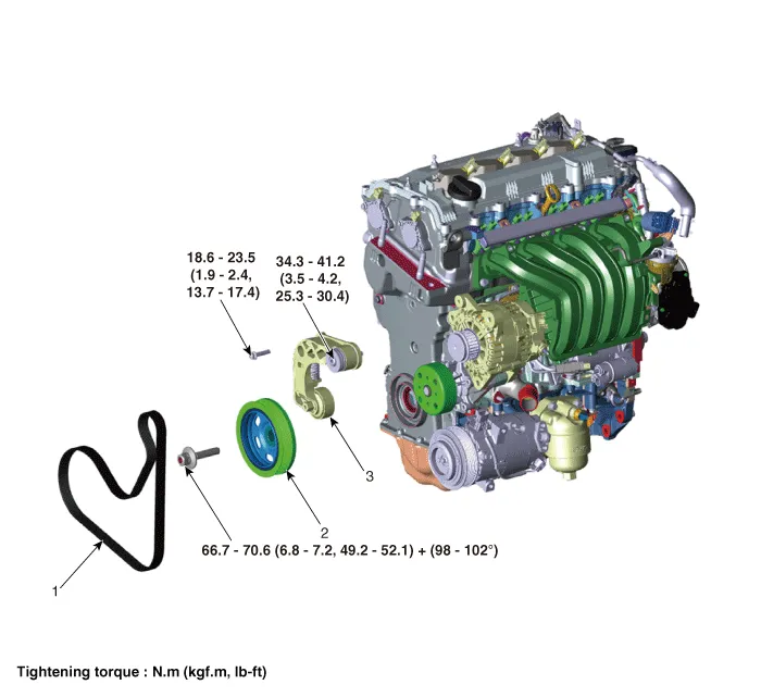
1. Drive belt
2. Crankshaft damper pulley
3. Drive belt tensioner
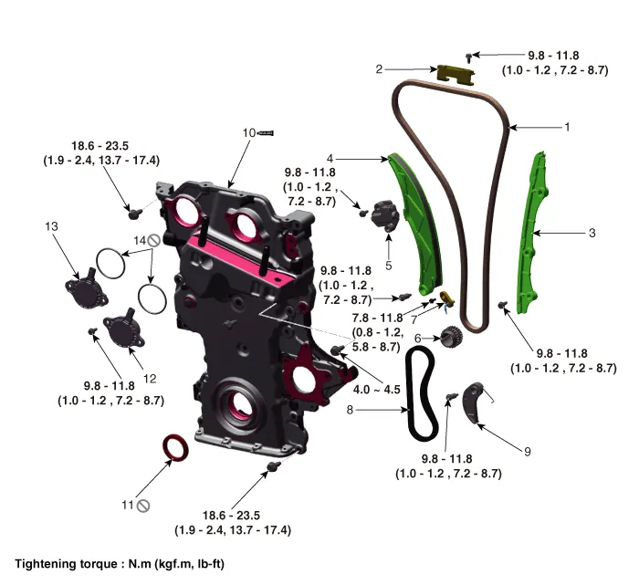
1. Timing chain
2 . Cam to cam guide
3. Timing chain guide
4. Timing chain tensioner arm
5. Timing chain tensioner
6. Crankshaft sprocket
7. Timing chain oil jet
8. Oil pump chain
9. Oil pump chain tensioner
10. Timing chain cover
11. Front oil seal
12. Intake variable force solenoid valve (VFS)
13. Exhaust variable force solenoid valves (VFS)
14. Variable force solenoid valves (VFS) O-ring
Drive Belt
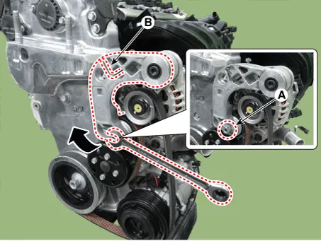
1.Install the wrench to the drive belt tensioner repair hole (A) and turn it clockwise.
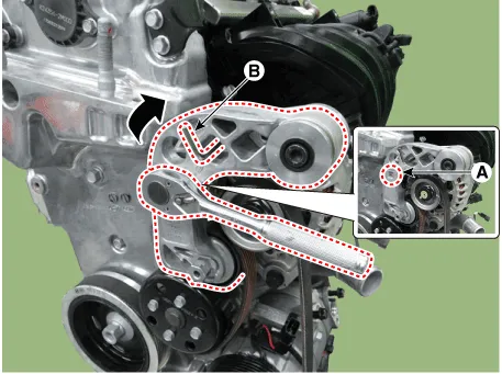

• Fix the drive belt tensioner by installing fixing pin (B) after turning the drive belt tensioner to clockwise.
• Use fixing pins that have the same outer diameter as a 6mm(0.2362 in.) hex wrench or a 6mm(0.2362 in.) hex wrench.
2.Remove the drive belt (A).
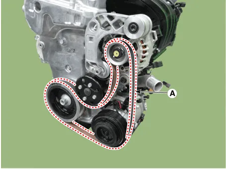

• When removing the drive belt, remove the drive belt from the water pump pulley.
3.Install in the reverse order of removal.

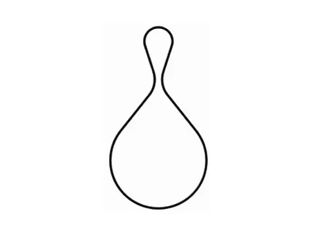
• When installation of drive belt, make the drive belt as a round hook shape bigger than alternater pulley as a picture down below. Then install it with following order of alternator → airconditioner compressor → crankshaft damper pulley → water pump → drive belt tensioner.
1.Remove the engine room under cover.(Refer to Engine and Transaxle Assembly - "Engine Room Under Cover")
2.Turn the spanner to clockwise after installing it to drive belt tensioner arm boss (A).

• Fix the drive belt tensioner by installing fixing pin (B) after turning the drive belt tensioner to clockwise.
• Use fixing pins that have the same outer diameter as a 6mm(0.2362 in.) hex wrench or a 6mm(0.2362 in.) hex wrench.
3.Remove the drive belt (A).


• When removing the drive belt, remove the drive belt from the water pump pulley.
4.Install in the reverse order of removal.

• When installation of drive belt, make the drive belt as a round hook shape bigger than alternater pulley as a picture down below. Then install it with following order of alternator → airconditioner compressor → crankshaft damper pulley → water pump → drive belt tensioner.

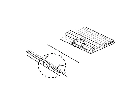
1.Visually check the belt for excessive wear, frayed cords etc.If any defect has been found, replace the drive belt.

• Cracks on the rib side of a belt are considered acceptable. If the belt has chunks missing from the ribs, it should be replaced.
Drive Belt Tensioner
1.Remove the drive belt.(Refer to Timing System - "Drive Belt")
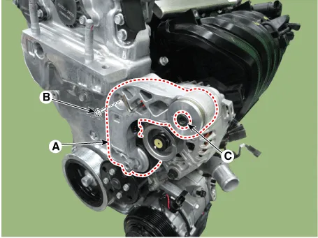
2.Remove the drive belt tensioner (A).
Tightening torque Bolt (B) : 18.6 - 23.5 N.m(1.9 - 2.4 kgf.m, 13.7 - 17.4 lb-ft)Bolt (C) : 34.3 - 41.2 N.m(3.5 - 4.2 kgf.m, 25.3 - 30.4 lb-ft)
3.Install in the reverse order of removal.
Crankshaft Damper Pulley
1.Remove the engine room under cover.(Refer to Engine and Transaxle Assembly - "Engine Room Under Cover")
2.Remove the drive belt.(Refer to Timing System - "Drive Belt")
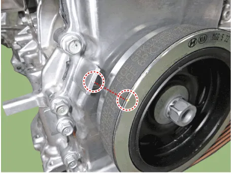
3.Remove the crankshaft damper pulley (A).
Tightening torque :66.7 - 70.6 N.m + 98 - 102°[6.8 - 7.2 kgf.m + 98 - 102°, 49.2 - 52.1 lb-ft + 98 - 102°]
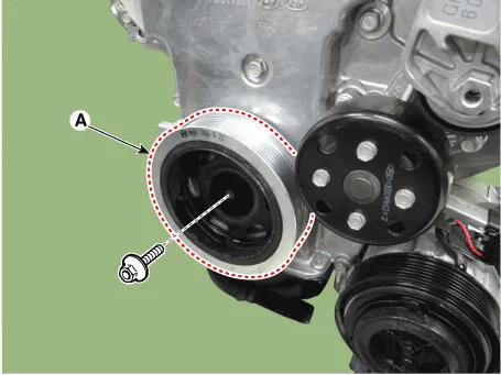

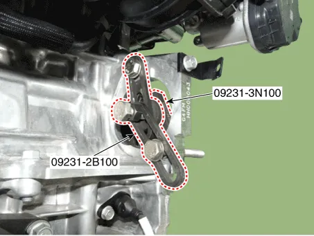
• Fix the ring gears using the SST (09231-2B100,09231-3N100) after removing the starter. Then remove the crankshaft damper pulley.
4.Install in the reverse order of removal.
Front Oil Seal
1.Remove the engine room under cover.(Refer to Engine and Transaxle Assembly - "Engine Room Under Cover")
2.Remove the drive belt.(Refer to Timing System - "Drive Belt")
3.Remove the crankshaft damper pulley.(Refer to Timing System - "Crankshaft Damper Pulley")
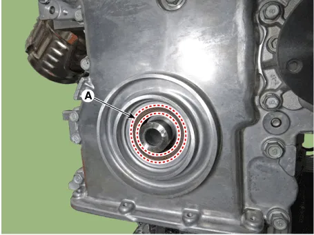
4.Remove the front oil seal (A).
5.Using the SST (0K231-2C200), install a new front oil seal.
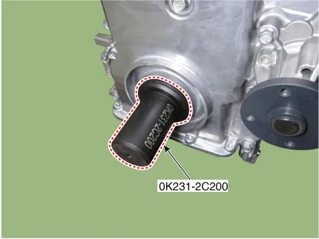

• Always use a new front oil seal.
6.Install in the reverse order of removal.
Timing Chain Cover

• Use fender covers to avoid damaging painted surfaces.
• To avoid damage, unplug the wiring connectors carefully while holding the connector portion.

• Mark all wiring and hoses to avoid misconnection.
1.Disconnect the battery negative terminal.
2.Remove the engine cover.(Refer to Engine and Transaxle Assembly - "Engine Cover")
3.Remove the engine room under cover.(Refer to Engine And Transaxle Assembly - "Engine Room Under Cover")
4.Drain the engine coolant.(Refer to Cooling System - "Coolant")
5.Drain the engine oil.(Refer to Lubrication System - "Engine Oil")
6.Remove the drive belt.(Refer to Timing System - "Drive Belt")
7.Remove the drive belt tensioner.(Refer to Timing System - "Drive Belt Tensioner")
8.Remove the alternator.(Refer to Engine Electrical System - "Alternator")
9.Remove the crankshaft damper pulley.(Refer to Timing System - "Crankshaft Damper Pulley")
10.Remove the engine hanger.
Tightening torque :18.6 - 23.5 N.m (1.9 - 2.4 kgf.m, 13.7 - 17.4 lb-ft)
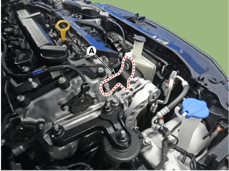
11.Disconnect the intake and exhaust variable force solenoid (VFS) valve connectors (A).
12.Remove the cylinder head cover.(Refer to Cylinder Head Assembly - "Cylinder Head Cover")
13.Remove the water pump.(Refer to Cooling System - "Water Pump")
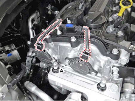
14.Remove the intake and exhaust variable force solenoid (VFS) valves (A).
Tightening torque :9.8 - 11.8 N.m (1.0 - 1.2 kgf.m, 7.2 - 8.7 lb-ft)
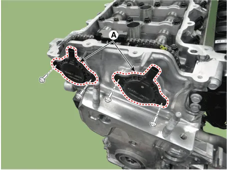

• The variable force solenoid (VFS) must be removed before removing the timing chain cover.
15.Remove the oil pan.(Refer to Lubrication System - "Oil Pan")
16.Remove the engine mounting bracket.(Refer to Engine And Transaxle Assembly - "Engine Mounting")
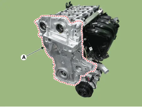
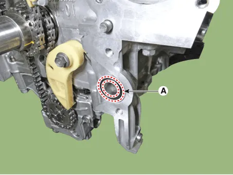
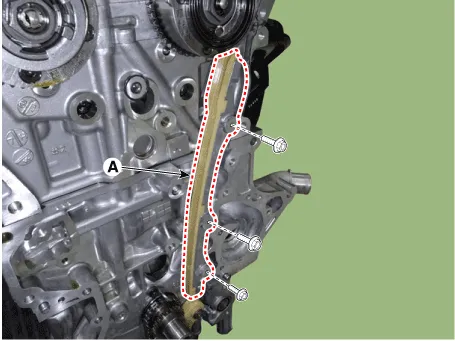
17.Remove the timing chain cover (A).
1.Install the new O-ring (A).
2.Install the timing chain cover.
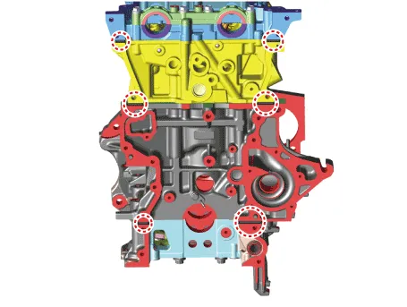
(1)Keep the liquid gasket sealing surfaces (cam carrier, cylinder head, cylinder block, lower crankcase) free from foreign matters, cured sealant, oil, dust, moisture and etc. Spray the cleaner on the sealing surface and wipe it off with a clean cloth.
(2)Apply liquid gasket sealant to an interface between cam carrier, cylinder head, cylinder block and lower crankcase.
Width : 3 - 5 mm (0.1181 - 0.1969 in.)Specification : LOCTITE 5900H / THREE BOND 1217H or above.
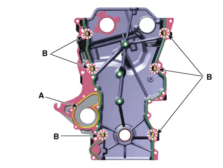
(3)Apply liquid sealant on timing chain cover. Then, assemble the part within 5 minutes of applying sealant.
Width Whole section : 2.5 - 3.5 mm (0.0984 - 0.1378 in)Section A : 1.5 - 2.5 mm (0.0591 - 0.0984 in)Section B : 3.5 - 4.5 mm (0.1378 - 0.1772 in)SpecificationWhole section : THREE BOND 1217H / M or above.Section A : THREE BOND 1282B / 1216E or above.
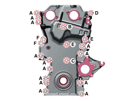
(4)The dowel pins on the cylinder block and holes on the timing chain cover should be used as a reference for assembling the timing chain cover to the exact position.
Tightening torque Bolt (A, B, C, D) : 18.6 - 23.5 N.m(1.9 - 2.4 kgf.m, 13.7 - 17.4 lb-ft)Bolt (E, F) : 39.2 - 44.1 N.m(4.0 - 4.5 kgf.m, 28.9 - 32.5 lb-ft)

• The firing and / or blow out test should not be performed within 30 minutes of assembling the timing chain cover.
3.Replace the front oil seal if necessary.(Refer to Timing System - "Front Oil Seal")
4.Install the other parts in the reverse order of removal.
5.Refill engine with engine oil.(Refer to Lubrication System - "Engine Oil")
6.Fill with engine coolant. (Refer to Cooling System - "Coolant")

• The coolant must be injected according to the integrated thermal management module (ITM) coolant filling method.
Timing Chain
1.Disconnect the battery negative terminal.
2.Turn the crankshaft damper pulley clockwise, and align its groove with the timing mark of the timing chain cover.
3.Remove the timing chain cover.(Refer to Timing System - "Timing Chain Cover")
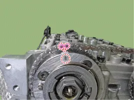
4.Remove the cam to cam guide (A).

5.Remove the timing chain tensioner (A) and remove the timing chain tensioner arm (B).
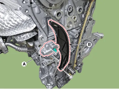

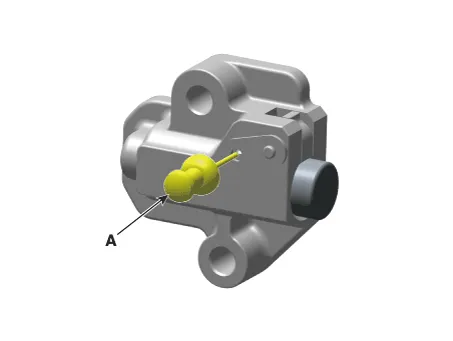
• Before the removal of timing chain tensioner, compress tensioner piston then remove the tensioner after fixing with fixing pin (A).
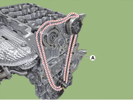
6.Remove the timing chain (A).
7.Remove the timing chain guide (A).
8.Remove the oil pump chain.(Refer to Lubrication System - "Oil Pump")
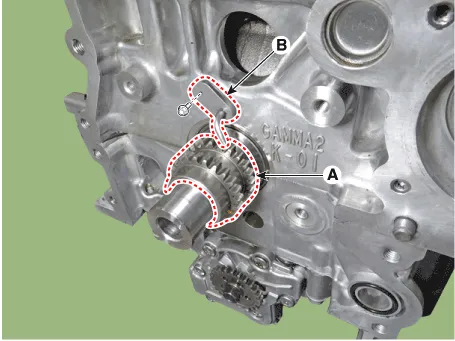
9.Remove the crankshaft sprocket (A) and timing chain oil jet (B).
1.Check the camshaft sprocket, crankshaft sprocket teeth for abnormal wear, cracks or damage. Replace if necessary.
2.Check a contact surface of the chain tensioner arm and guide for abnormal wear, cracks or damage. Replace if necessary.
3.Check the hydraulic tensioner for its piston stroke and ratchet operation. Replace if necessary.
1.Install the crankshaft sprocket (A) and timing chain oil jet (B).
Tightening torque : 7.8 - 11.8 N.m (0.8 - 1.2 kgf.m, 5.8 - 8.7 lb-ft)

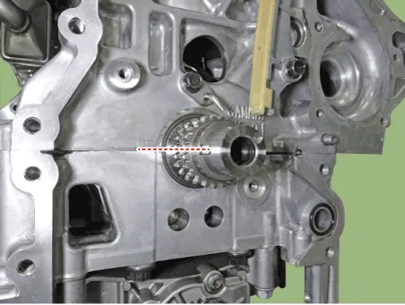
2.Place the crankshaft key at the left 180°.
3.Install the oil pump chain.(Refer to Lubrication System - "Oil Pump")
4.Install the timing chain guide (A).
Tightening torque :9.8 - 11.8 N.m (1.0 - 1.2 kgf.m, 7.2 - 8.7 lb-ft)

5.Install the timing chain (A).


• When installing the timing chain, be sure that the timing mark
of each sprocket is matched with the timing mark (color link) of the
timing chain.
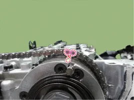

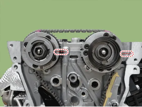
• When installing the timing chain, check that the TDC mark on the front of the intake and exhaust CVVT is positioned at 0°(pointing right).

6.Install the timing chain tensioner (A) and timing chain tensioner arm (B).
Tightening torque : 9.8 - 11.8 N.m (1.0 - 1.2 kgf.m, 7.2 - 8.7 lb-ft)


• Install the timing chain tensioner and remove the pin (B).

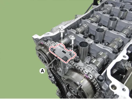
7.Install the cam to cam guide (A).
Tightening torque :9.8 - 11.8 N.m (1.0 - 1.2 kgf.m, 7.2 - 8.7 lb-ft)
8.Check if the TDC mark at the front of intake and exhaust CVVT on right side 0° by turning crankshaft twice to clockwise.
9.Install the timing chain cover.(Refer to Timing System - "Timing Chain Cover")
10.Install the other parts in the reverse order of removal.


Other information:
Hyundai Accent (HC) (2017 - 2022) Service Manual: Tire Pressure Monitoring System (TPMS)
(1) Low Tire Pressure / TPMS Malfunction Indicator Lamp (2) Low Tire Pressure / Tire Pressure Monitor / TPMS Malfunction Display (shown on the cluster LCD display)Some Hyundai Accent models use a Smart Key, which you can use to lock or unlock a door (and trunk) and start the engine. For best performance, keep the Smart Key close to you and avoid storing it near strong electromagnetic sources. 1. Door Lock 2. Door Unlock 3. Trunk Unlock 4. Panic Locking To lock your Hyundai Accent using the Smart Key system: 1.
Contents
- Components and Components Location
- Drive Belt
- Drive Belt Tensioner
- Crankshaft Damper Pulley
- Front Oil Seal
- Timing Chain Cover
- Timing Chain
Categories
- Manuals Home
- Hyundai Accent Owners Manual
- Hyundai Accent Service Manual
- Questions & Answers
- Video Guides
- Useful Resources
- New on site
- Most important about car
- Privacy Policy

0.0069