Hyundai Accent (HC): Engine Control / Fuel System / Engine Control System
Contents:
- Components and Components Location
- Description and Operation
- Engine Control Module (ECM)
- Mass Air Flow Sensor (MAFS)
- ETC (Electronic Throttle control) System
- Manifold Absolute Pressure Sensor (MAPS)
- Intake Air Temperature Sensor (IATS)
- Engine Coolant Temperature Sensor (ECTS)
- Crankshaft Position Sensor (CKPS)
- Camshaft Position Sensor (CMPS)
- Knock Sensor (KS)
- Heated Oxygen Sensor (HO2S)
- Accelerator Position Sensor (APS)
- Fuel Tank Pressure Sensor (FTPS)
- Injector
- Purge Control Solenoid Valve (PCSV)
- CVVT Oil Control Valve (OCV)
- Variable Force Solenoid (VFS)
- Variable Intake Solenoid (VIS) Valve
- Electric EGR Control Valve
- Canister Close Valve (CCV)
- Thermal Management Module (TMM) Motor
Components and Components Location
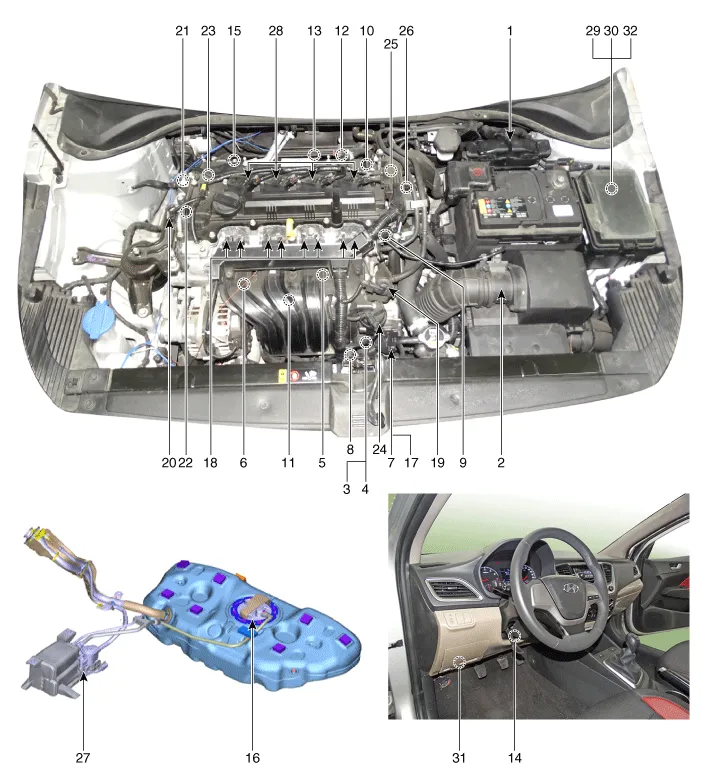
1. ECM (Engine Control Module)
2. Mass Air Flow Sensor (MAFS)
3. Manifold Absolute Pressure Sensor (MAPS)
4. Intake Air Temperature Sensor (IATS)
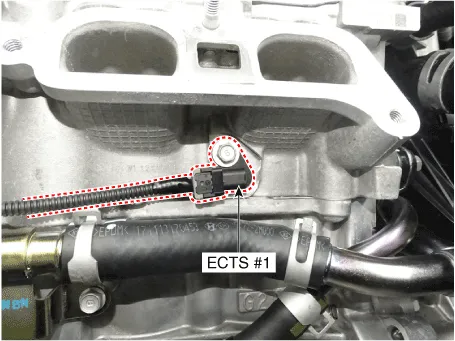
5. Engine Coolant Temperature Sensor (ECTS) #1
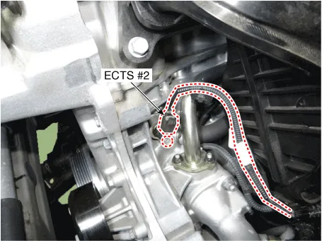
6. Engine Coolant Temperature Sensor (ECTS) #2
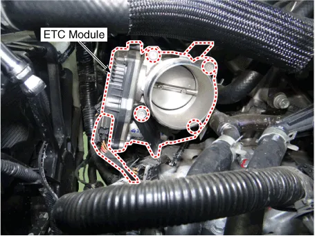
7. Throttle Position Sensor (TPS) [integrated into ETC Module]
8. Crankshaft Position Sensor (CKPS)
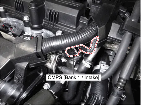
9. Camshaft Position Sensor (CMPS) [Bank 1 / Intake]
10. Camshaft Position Sensor (CMPS) [Bank 1 / Exhaust]
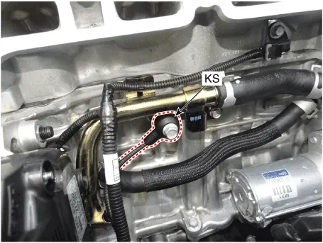
11. Knock Sensor (KS)
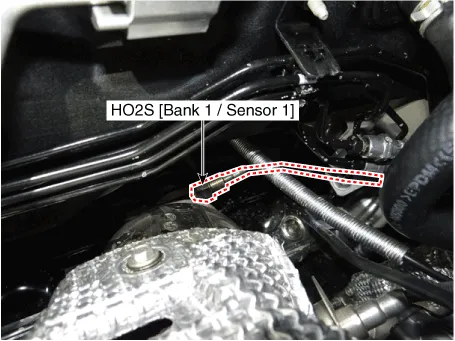
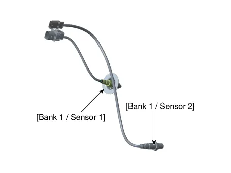
12. Heated Oxygen Sensor (HO2S) [Bank 1 / Sensor 1]
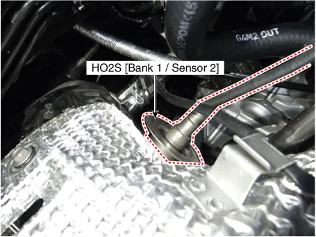
13. Heated Oxygen Sensor (HO2S) [Bank 1 / Sensor 2]
14. Accelerator Position Sessor (APS)
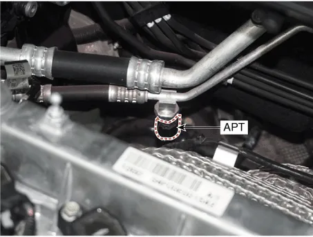
15. A/C Pressure Transducer (APT)
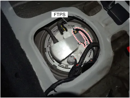
16. Fuel Tank Pressure Sensor (FTPS)
17. ETC Motor [integrated into ETC Module]
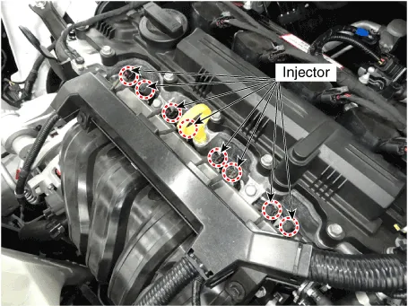
18. Injector
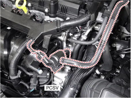
19. Purge Control Solenoid Valve (PCSV)
20. Variable Force Solenoid (VFS) [Bank 1 / Intake]
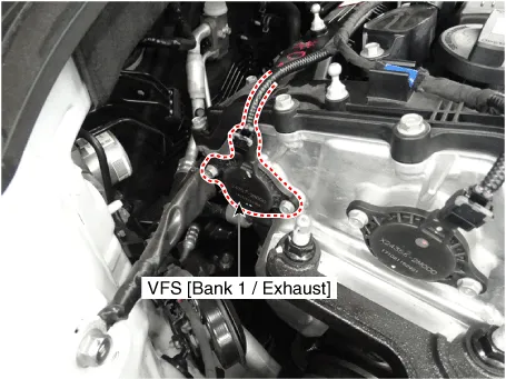
21. Variable Force Solenoid (VFS) [Bank 1 / Exhaust]
22. CVVT Oil Control Valve (OCV) [Bank 1 / Intake]
23. CVVT Oil Control Valve (OCV) [Bank 1 / Exhaust]
24. Variable Intake Solenoid (VIS) Valve
25. Electric EGR Control Valve
26. Thermal Management Module (TMM) Motor
27. Canister Close Valve (CCV)
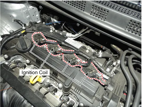
28. Ignition Coil
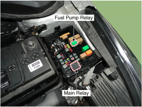
29. Main Relay
30. Fuel Pump Relay
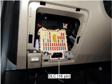
31. Data Link Connector (DLC) [16-Pin]
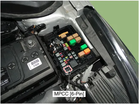
32. Multi-Purpose Connector [6-pin]
| 1. ECM (Engine Control Module) | 2. Mass Air Flow Sensor (MAFS) |
|
|
| 3. Manifold Absolute Pressure Sensor (MAPS) 4. Intake Air Temperature Sensor (IATS) | 5. Engine Coolant Temperature Sensor (ECTS) #1 |
|
|
| 6. Engine Coolant Temperature Sensor (ECTS) #2 | 7. Throttle Position Sensor (TPS) [integrated into ETC Module] 17. ETC Motor [integrated into ETC Module] |
|
|
| 8. Crankshaft Position Sensor (CKPS) | 9. Camshaft Position Sensor (CMPS) [Bank 1 / Intake] |
|
|
| 10. Camshaft Position Sensor (CMPS) [Bank 1 / Exhaust] | 11. Knock Sensor (KS) |
|
|
| 12. Heated Oxygen Sensor (HO2S) [Bank 1 / Sensor 1] | 13. Heated Oxygen Sensor (HO2S) [Bank 1 / Sensor 2] |
|
|
| 14. Accelerator Position Sessor (APS) | 15. A/C Pressure Transducer (APT) |
|
|
| 16. Fuel Tank Pressure Sensor (FTPS) | 18. Injector |
|
|
| 19. Purge Control Solenoid Valve (PCSV) | 20. Variable Force Solenoid (VFS) [Bank 1 / Intake] |
|
|
| 21. Variable Force Solenoid (VFS) [Bank 1 / Exhaust] | 22. CVVT Oil Control Valve (OCV) [Bank 1 / Intake] 23. CVVT Oil Control Valve (OCV) [Bank 1 / Exhaust] |
|
|
| 24. Variable Intake Solenoid (VIS) Valve | 25. Electric EGR Control Valve |
|
|
| 26. Thermal Management Module (TMM) Motor | 27. Canister Close Valve (CCV) |
|
|
| 28. Ignition Coil | 27. Main Relay 28. Fuel Pump Relay |
|
|
| 31. Data Link Connector (DLC) [16-Pin] | 32. Multi-Purpose Connector [6-pin] |
|
|


Description and Operation ➤
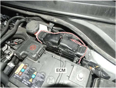
Engine Control Module (ECM) ➤
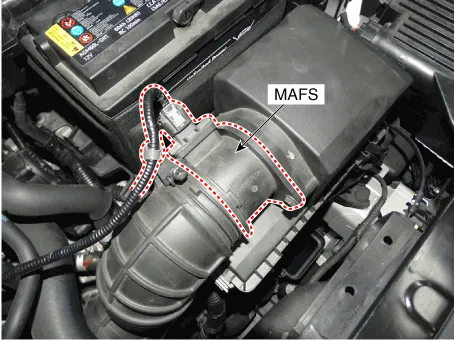
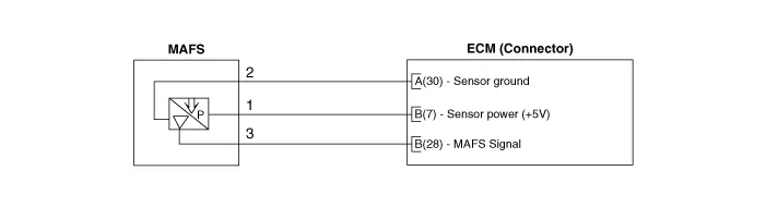
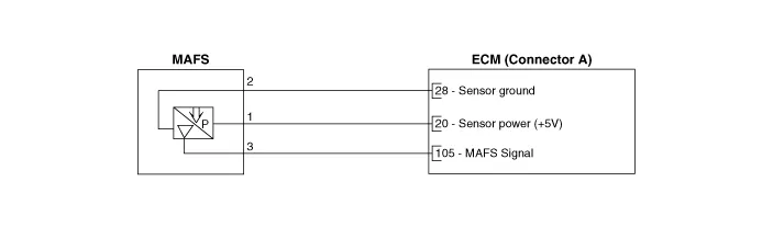
Mass Air Flow Sensor (MAFS)
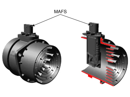

1.Check the MAFS visually.
ŌĆō Mounting direction correct.
ŌĆō Any contamination, corrosion or damage on connector.
ŌĆō Air cleaner's clogging or wet.
ŌĆō MAFS cylinder's deforming or blocking by any foreign material.
2.Check any leakage on intake system and intercooler system.
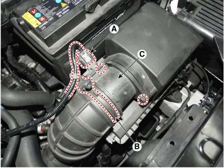
1.Turn the ignition switch OFF and disconnect the battery (-) cable.
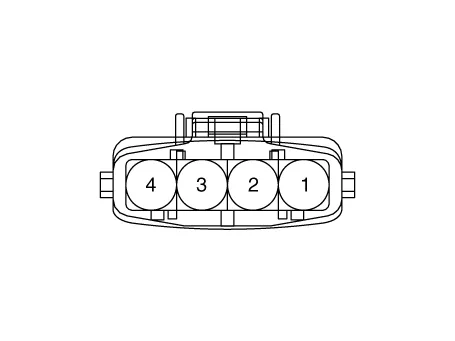
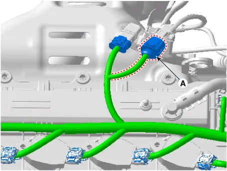
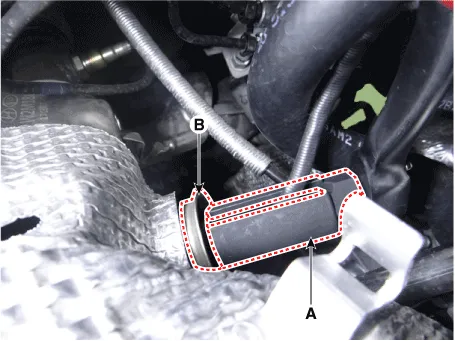
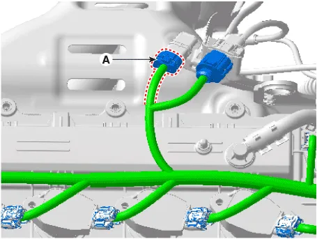
2.Disconnect the MAFS connector (A).
3.Remove the clamp (B).
4.Remove the installation bolts and then remove the MAFS (C).
Mass air flow sensor clamp installation bolt :2.9 - 4.9 N.m (0.3 - 0.5 kgf.m, 2.2 - 3.6 lb-ft)Mass air flow sensor installation bolt :2.9 - 4.9 N.m (0.3 - 0.5 kgf.m, 2.2 - 3.6 lb-ft)

ŌĆó Install the component with the specified torques.
ŌĆó Note that internal damage may occur when the component is dropped. In this case, use it after inspecting.

ŌĆó Be careful not to damage the sensing element and the honey cell.
1.Install in the reverse order of removal.
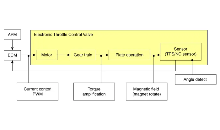
ETC (Electronic Throttle control) System
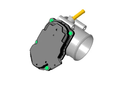
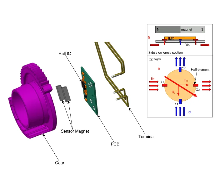
[ETC Motor]
| Item | Sensor Resistance |
| Coil Resistance (Ōä”) | 1.4 ~ 1.5 [25 ┬▒ 5┬░C (77 ┬▒ 41┬░F)] |
| Items | Fail-safe | |
| ETC Motor | Throttle valve stuck at 9.2┬░ | |
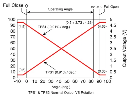
| TPS | TPS 1 fault | Replace it with TPS 2 |
| TPS 2 fault | Replace it with TPS 1 | |
| TPS 1, 2 fault | Throttle valve stuck at 9.2┬░ | |

ŌĆó When throttle valve is stuck at 9.2┬░, engine speed is limited at 1,200 ~ 1,700 rpm.

1.Connect a GDS on the Data Link Connector (DLC).
2.Start engine and check output voltages of TPS 1 and 2 at C.T and W.O.T.
Specification : Refer to Specification Section.
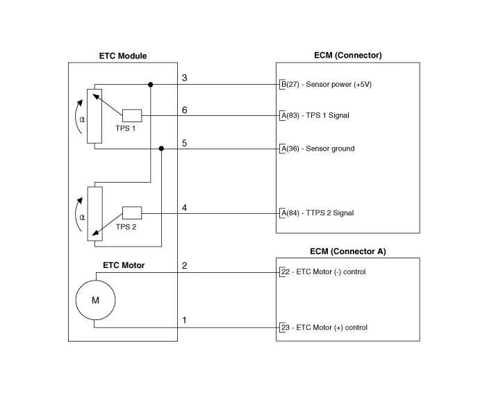
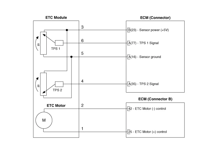
1.Turn the ignition switch OFF.
2.Disconnect the ETC module connector.
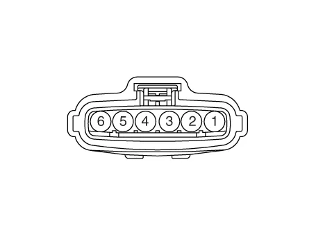
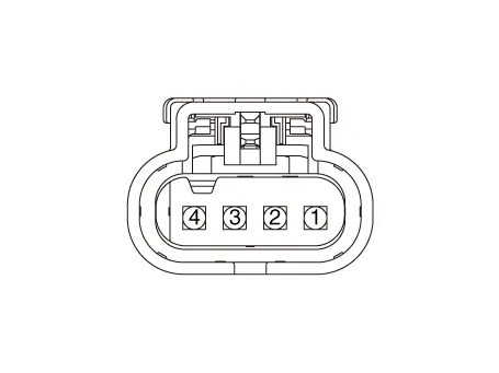
3.Measure resistance between the ETC module terminals 1 and 2.
4.Check that the resistance is within the specification.
Specification : Refer to Specification Section.
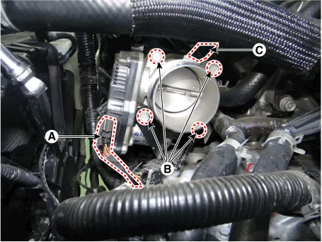
1.Turn the ignition switch OFF and disconnect the battery negative (-) cable.
2.Remove the resonator and the air intake hose.(Refer to Engine Mechanical System - "Air Cleaner")
3.Disconnect the ETC module connector (A).
4.Remove the installation bolts and then remove the ETC module (B) from the engine.
5.Disconnect the vapor hose (C).
Electronic throttle body Installation bolt :9.8 ~ 11.8 N.m (1.0 ~ 1.2 kgf.m, 7.2 ~ 8.7 lb-ft)
1.Remove the ETC Module.(Refer to Engine Control System - "ETC System")
2.Keep the ETC module plate (A) open.
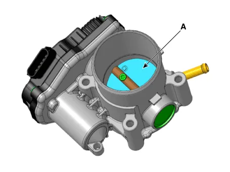
3.Clean the pollutant in the throttle body with a soft cloth moistened with cleaning fluid.
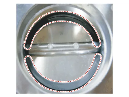

ŌĆó Do not spray cleaning fluid directly onto ETC. Use a lint free cloth moistened with cleaning fluid.
ŌĆó Be careful not to clean the coating fluid around the shaft. If coating fluid is removed, idling control failure might occur by foreign substance inflow or excessive air leakage.
4.After cleaning, re-install the ETC module and then perform the ETC module learning procedure.(Refer to Engine Control System - "ETC System" - Adjustment)

ŌĆó Install the component to the specified torques.
ŌĆó Note that internal damage may occur when the component is dropped. In this case, use it after inspecting.
1.Install in the reverse order of removal.
1.Wait for 1 minute with the ignition switch ON.
2.Start the engine and hold the idle status for 15 minutes.
3.Waif for 1 minute with the ignition switch OFF.
4.Restart the engine, and check that the idle speed is stable.

ŌĆó If the ETC module learning procedure is not performed after replacing or reinstalling the ETC module, MIL illumination with DTCs may occur.
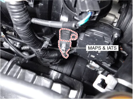
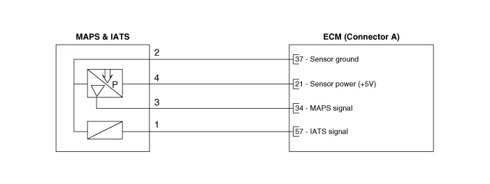
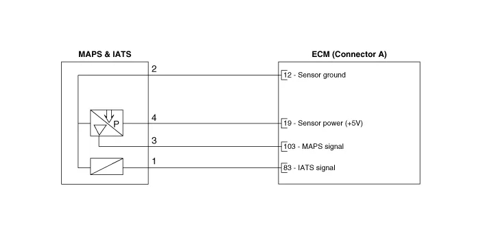
Manifold Absolute Pressure Sensor (MAPS)
| Pressure (kPa) | Output Voltage (V) |
| 10 | 0.5 |
| 62.5 | 2.5 |
| 115 | 4.5 |
1.Connect a GDS on Data Link Connector (DLC).
2.Check MAPS output voltage at idle and IG ON.
| Condition | Output Voltage (V) |
| IG ON | 3.9 ~ 4.1 |
| Idle | 0.8 ~ 1.6 |
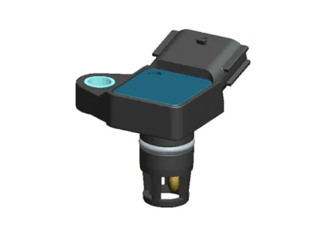
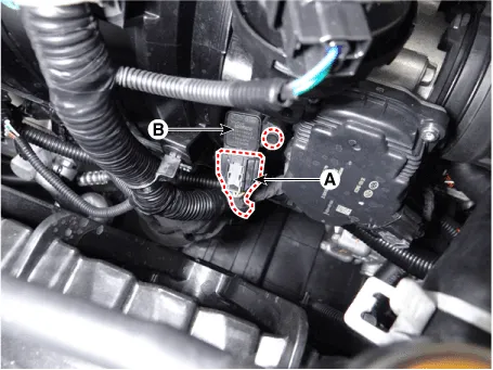
1.Turn the ignition switch OFF and disconnect the battery negative (-) cable.
2.Disconnect the manifold absolute pressure sensor connector (A).
3.Remove the installation bolt (B), and then remove the sensor from the surge tank.
Manifold absolute pressure sensor installation bolt :6.9 ~ 8.8 N.m (0.7 ~ 0.9 kgf.m, 5.1 ~ 6.5 lb-ft)

ŌĆó Install the component with the specified torques.
ŌĆó Note that internal damage may occur when the component is dropped. In this case, use it after inspecting.

ŌĆó Insert the sensor in the installation hole and be careful not to damage when installation.
1.Install in the reverse order of removal.
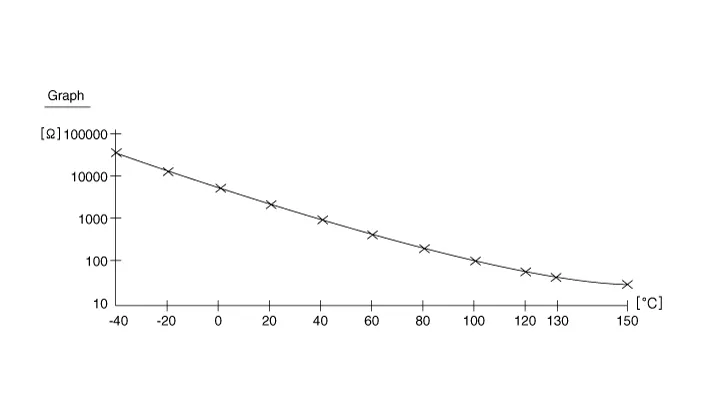
Intake Air Temperature Sensor (IATS)
| Temperature [┬░C (┬░F)] | Resistance (k╬®) |
| -40 (-40) | 38.88 ~ 50.77 |
| -20 (-4) | 13.19 ~ 16.82 |
| 0 (32) | 5.11 ~ 6.11 |
| 20 (68) | 2.19 ~ 2.69 |
| 40 (104) | 1.02 ~ 1.26 |
| 60 (140) | 0.51 ~ 0.64 |
| 80 (176) | 0.27 ~ 0.35 |


1.Turn ignition switch OFF.
2.Disconnect IATS connector.
3.Measure resistance between IATS terminals 3 and 4.
4.Check that the resistance is within the specification.
Specification : Refer to "Specification"
1.Turn the ignition switch OFF and disconnect the battery negative (-) cable.
2.Disconnect the manifold absolute pressure sensor connector (A).
3.Remove the installation bolt (B), and then remove the sensor from the surge tank.
Manifold absolute pressure sensor installation bolt :6.9 ~ 8.8 N.m (0.7 ~ 0.9 kgf.m, 5.1 ~ 6.5 lb-ft)


ŌĆó Install the component with the specified torques.
ŌĆó Note that internal damage may occur when the component is dropped. In this case, use it after inspecting.

ŌĆó Insert the sensor in the installation hole and be careful not to damage when installation.
1.Install in the reverse order of removal.
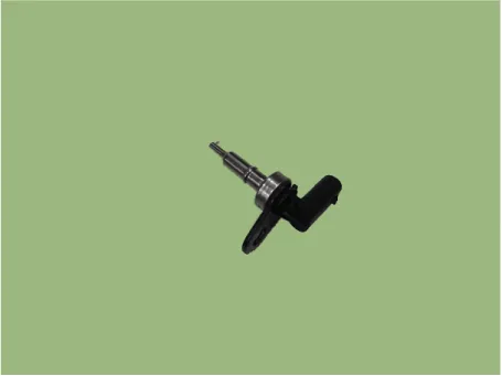
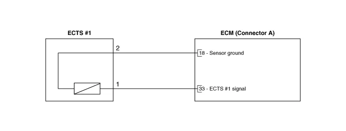
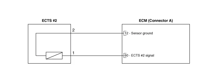
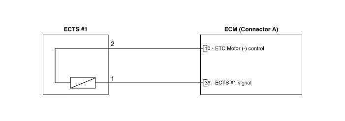
Engine Coolant Temperature Sensor (ECTS)
| Temperature [┬░C (┬░F)] | Resistance (k╬®) |
| -40 (-40) | 41.74 ~ 54.54 |
| -30 (-22) | 23.54 ~ 29.94 |
| -20 (-4) | 14.13 ~ 16.83 |
| -10 (14) | 8.39 ~ 10.22 |
| 0 (32) | 5.28 ~ 6.29 |
| 10 (50) | 3.42 ~ 4.00 |
| 20 (68) | 2.31 ~ 2.59 |
| 30 (86) | 1.55 ~ 1.86 |
| 40 (104) | 1.08 ~ 1.21 |
| 50 (122) | 0.77 ~ 0.85 |
| 60 (140) | 0.56 ~ 0.61 |
| 70 (158) | 0.41 ~ 0.44 |
| 80 (176) | 0.31 ~ 0.33 |
| 90 (194) | 0.23 ~ 0.25 |
| 100 (212) | 0.18 ~ 0.19 |

1.Turn ignition switch OFF.
2.Disconnect ECTS connector.
3.Remove the ECTS.
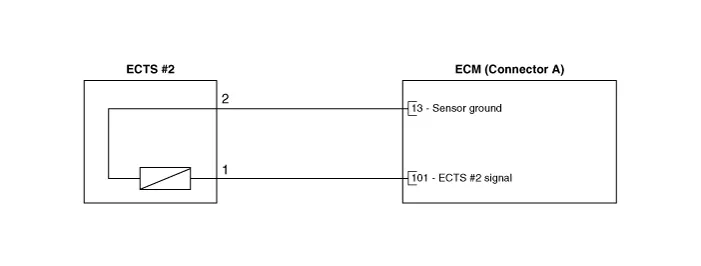
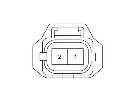
4.After immersing the thermistor of the sensor into engine coolant, measure resistance between ECTS terminals 1 and 2.
5.Check that the resistance is within the specification.
Specification : Refer to "Specification"
1.Turn the ignition switch OFF and disconnect the battery negative (-) cable.
2.Remove the intake manifold.(Refer to Engine Mechanical System - "Intake Manifold")
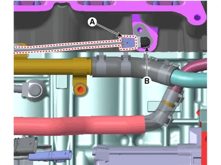
3.Disconnect the engine coolant temperature sensor connector (A).
4.Remove the installation bolt, and then remove the sensor (B) from the cylinder block.
Engine coolant temperature sensor installation :9.8 - 11.8 N.m (1.0 - 1.2 kgf.m, 7.2 - 8.7 lb-ft)
1.Turn the ignition switch OFF and disconnect the battery negative (-) cable.
2.Remove the alternator.(Refer to Engine Electrical System - "Alternator")
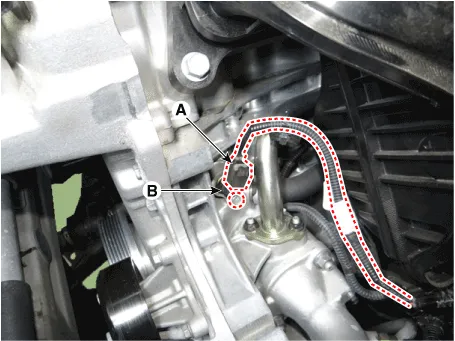
3.Disconnect the engine coolant temperature sensor connector (A).
4.Remove the installation bolt, and then remove the sensor (B) from the cylinder block.
Engine coolant temperature sensor installation :9.8 - 11.8 N.m (1.0 - 1.2 kgf.m, 7.2 - 8.7 lb-ft)

ŌĆó Install the component with the specified torques.
ŌĆó Note that internal damage may occur when the component is dropped. If the component has been dropped, inspect before installing.

ŌĆó Insert the sensor in the installation hole and be careful not to damage.
1.Install in the reverse order of removal.
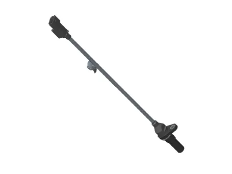
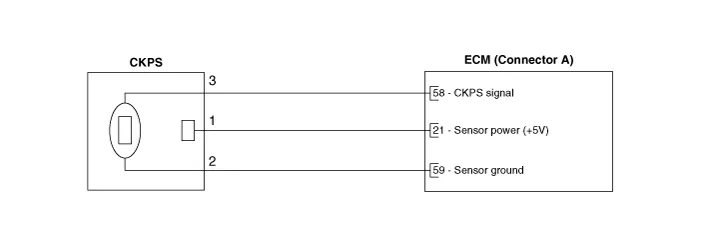
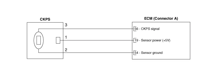
Crankshaft Position Sensor (CKPS)

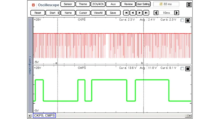


1.Check signal waveform of CKPS and CMPS using a GDS.
Specification : Refer to "Waveform"
1.Turn the ignition switch OFF and disconnect the battery negative (-) cable.
2.Remove the engine room under cover.(Refer to Engine and Transaxle Assembly - "Engine Room Under Cover")
3.Disconnect the crankshaft position sensor connector (A).
4.Remove the installation bolt (B), and then remove the crankshaft position sensor.
Crankshaft position sensor installation bolt :7.8 ~ 11.8 N.m (0.8 ~ 1.2 kgf.m, 5.8 ~ 8.7 lb-ft)

ŌĆó Install the component with the specified torques.
ŌĆó Note that internal damage may occur when the component is dropped. If the component has been dropped, inspect before installing.

ŌĆó Apply the engine coolant to the O-ring.

ŌĆó Insert the sensor in the installation hole and be careful not to damage.
1.Install in the reverse order of removal.
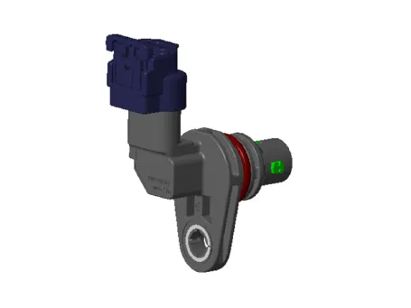
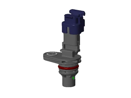
Camshaft Position Sensor (CMPS)
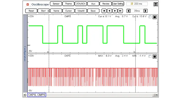

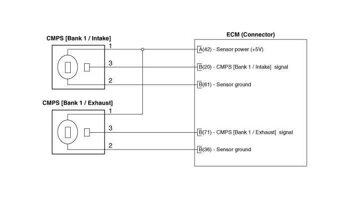


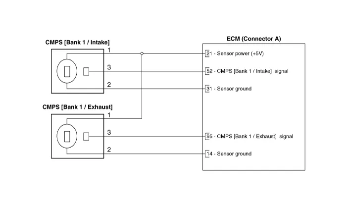

1.Check signal waveform of CKPS and CMPS using a scan tool.
Specification : Refer to "Waveform"

ŌĆó DONŌĆÖT remove the camshaft position sensor during engine running or right after engine stops, or a scald by the flowed out engine oil may occur.
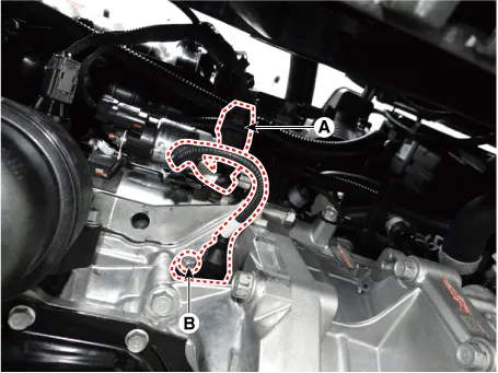
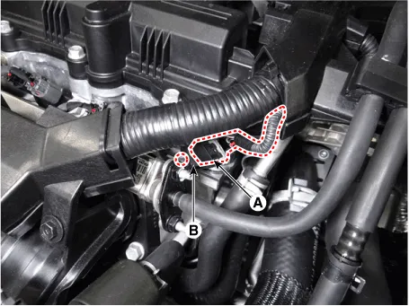
1.Turn the ignition switch OFF and disconnect the battery negative (-) cable.
2.Disconnect the camshaft position sensor connector (A).
3.Remove the installation bolt, and then remove the sensor (B).
Camshaft position sensor installation bolt :7.8 ~ 11.8 N.m (0.8 ~ 1.2 kgf.m, 5.8 ~ 8.7 lb-ft)
1.Turn the ignition switch OFF and disconnect the battery negative (-) cable.
2.Disconnect the camshaft position sensor connector (A).
3.Remove the installation bolt, and then remove the sensor (B).
Camshaft position sensor installation bolt :7.8 ~ 11.8 N.m (0.8 ~ 1.2 kgf.m, 5.8 ~ 8.7 lb-ft)

ŌĆó Install the component with the specified torques.
ŌĆó Note that internal damage may occur when the component is dropped. If the component has been dropped, inspect before installing.

ŌĆó Apply the engine coolant to the O-ring.

ŌĆó Insert the sensor in the installation hole and be careful not to damage.
1.Install in the reverse order of removal.
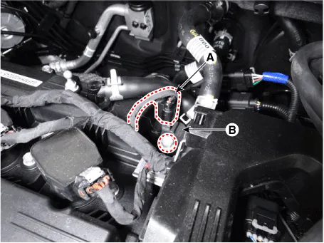
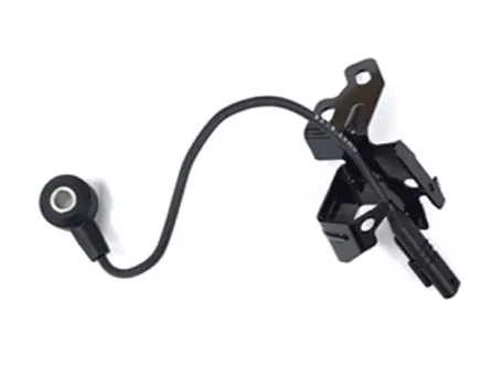
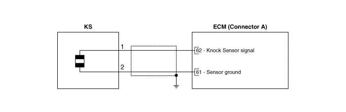
Knock Sensor (KS)
| Item | Specification | Remarks |
| Capacitance (pF) | 850 ~ 1150 | 1 Khz |
| Insulation registance (MŌä”) | 850 ~ 1150 | Pin to Body |

1.Turn the ignition switch OFF and disconnect the battery negative (-) cable.
2.Remove the intake manifold.(Refer to Engine Mechanical System - "Intake Manifold")
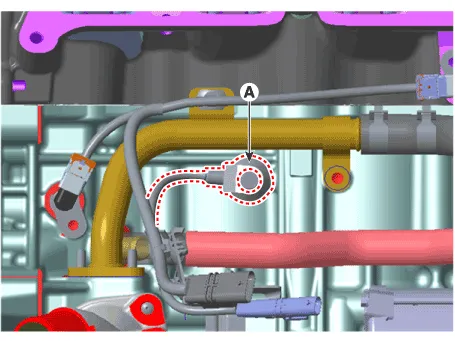
3.Remove the installation bolt (A), and then remove the sensor from the cylinder block.
Knock sensor installation bolt :18.6 ~ 24.5 N.m (1.9 ~ 2.5 kgf.m, 13.7 ~ 18.1 lb-ft)

ŌĆó Install the component with the specified torques.
ŌĆó Note that internal damage may occur when the component is dropped. In this case, use it after inspecting.
1.Install in the reverse order of removal.
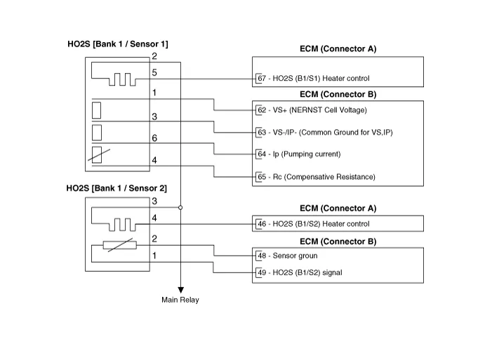
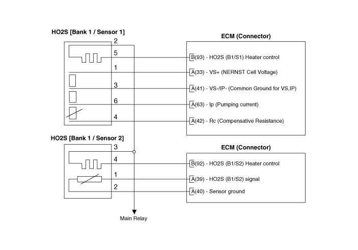
Heated Oxygen Sensor (HO2S)
| Item | Specification |
| Heater Resistance (Ōä”) | Approx. 2.5 [20┬░C (68┬░F)] |
| Item | Specification |
| Heater Resistance (Ōä”) | Approx. 3.0 [20┬░C (68┬░F)] |


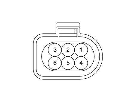
1.Turn the ignition switch OFF.
2.Disconnect the HO2S connector.
3.Measure resistance between HO2S heater terminals 3 and 4.
4.Check that the resistance is within the specification.
| Item | Specification |
| Heater Resistance (Ōä”) | Approx. 2.5 [20┬░C (68┬░F)] |
| Item | Specification |
| Heater Resistance (Ōä”) | Approx. 3.0 [20┬░C (68┬░F)] |
1.Turn the ignition switch OFF and disconnect the battery negative (-) cable.
2.Disconnect the heated oxygen sensor connector (A).
3.Remove the heated oxygen sensor (B) using the special tool (A) [SST No. : 09392-1Y100] as shown below.

ŌĆó Note that the SST (Part No. : 09392-2H100 or 09392-1Y100) is useful when removing the heated oxygen sensor.
Heated oxygen sensor installation :40.0 ~ 60.0 N.m (4.1 ~ 6.1 kgf.m, 29.5 ~ 44.3 lb-ft)
1.Turn the ignition switch OFF and disconnect the battery negative (-) cable.
2.Disconnect the heated oxygen sensor connector (A).
3.Lift the vehicle.
4.Remove the heated oxygen sensor (B) using the special tool (A) [SST No. : 09392-1Y100] as shown below.

ŌĆó Note that the SST (Part No. : 09392-2H100 or 09392-1Y100) is useful when removing the heated oxygen sensor.
Heated oxygen sensor installation :40.0 ~ 60.0 N.m (4.1 ~ 6.1 kgf.m, 29.5 ~ 44.3 lb-ft)

ŌĆó Install the component with the specified torques.
ŌĆó Note that internal damage may occur when the component is dropped. In this case, use it after inspecting.

ŌĆó DONŌĆÖT use a cleaner, spray, or grease to sensing element and connector of the sensor because oil component in them may malfunction the sensor performance.
ŌĆó Sensor and its wiring may be damaged in case of contacting with the exhaust system (Exhaust Manifold, Catalytic Converter, and so on).
1.Install in the reverse order of removal.
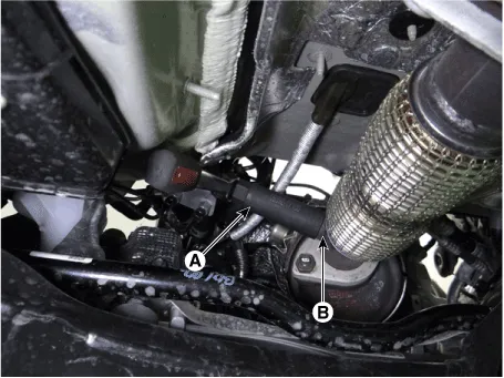
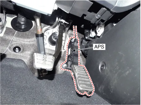
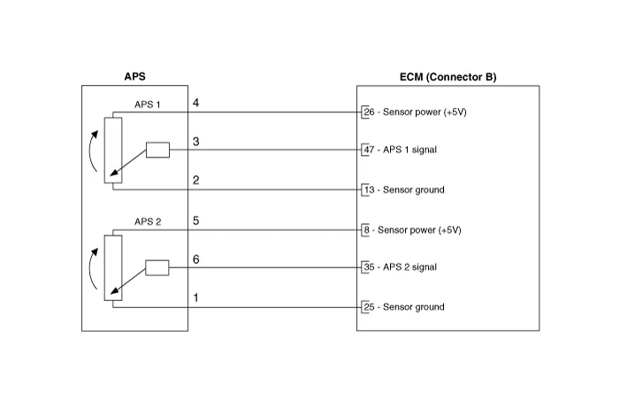
Accelerator Position Sensor (APS)
| Items | Specification | |
| APS 1 | APS 2 | |
| C.T | 0.7 ~ 0.8 | 0.33 ~ 0.43 |
| W.O.T | 4.13 ~ 4.22 | 2.04 ~ 2.13 |
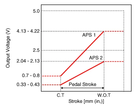
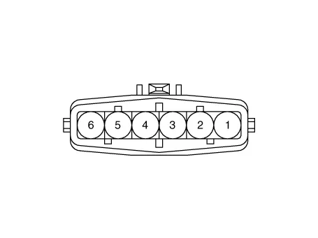
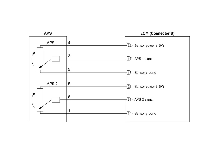

1.Connect the GDS on the Diagnosis Link Connector (DLC).
2.Start engine and check output voltages of APS 1 and 2 at C.T and W.O.T.
Specification : Refer to Specification Section.
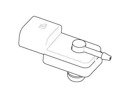
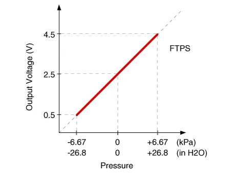
Fuel Tank Pressure Sensor (FTPS)
| Pressure [kPa (kgf/cm┬▓, in H2O)] | Output Voltage (V) |
| -6.67 (-0.068, -26.8) | 0.5 |
| 0 | 2.5 |
| +6.67 (0.068, 26.8) | 4.5 |
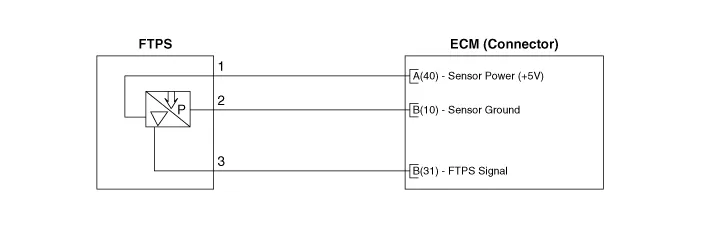

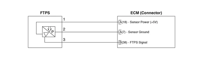
1.Connect the GDS on the Data Link Connector (DLC).
2.Measure the output voltage of the FTPS.
Specification : Refer to "Specification"
1.Turn the ignition switch OFF and disconnect the battery negative (-) cable.
2.Remove the rear seat.(Refer to Body - "Rear Seat")
3.Remove the fuel pump service cover (A).

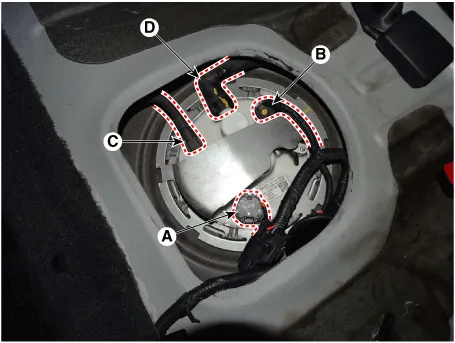
4.Disconnect the fuel pump connector (A).
5.Disconnect the fuel tank pressure sensor connector (B).
6.Disconnect the fuel feed tube quick connector (C).
7.Disconnect the vapor tube quick connector (D).
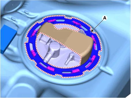
8.Remove the locking ring (A) by using the SST [SST.: 09310-F3100] from the fuel tank.

ŌĆó When removing the plate cover, be careful not to damage the fuel tank and fuel pump.
ŌĆó When removing the plate cover, press the upper area with hand and rotate the wrench counter clockwise.
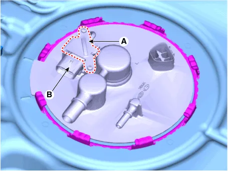
9.Remove the fule tank pressure sensor bracket (A).
10.Remove the fule tank pressure sensor (B).

ŌĆó Install the component with the specified torques.
ŌĆó Note that internal damage may occur when the component is dropped. In this case, use it after inspecting.

ŌĆó Insert the sensor in the installation hole and be careful not to damage when installation.
1.Install in the reverse order of removal.
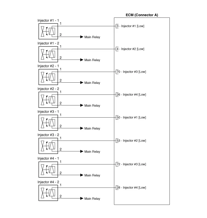
Injector

| Item | Specification |
| Coil Resistance (Ōä”) | 11.4 ~ 12.6 [20┬░C (68┬░F)] |


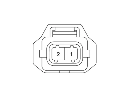
1.Turn ignition switch OFF.
2.Disconnect injector connector.
3.Measure resistance between injector terminals 1 and 2.
4.Check that the resistance is within the specification.
| Item | Specification |
| Coil Resistance (Ōä”) | 11.4 ~ 12.6 [20┬░C (68┬░F)] |

ŌĆó In case of removing the high pressure fuel pump, high pressure fuel pipe, delivery pipe, and injector, there may be injury caused by leakage of the high pressure fuel. So don't do any repair work right after engine stops.
1.Turn the ignition switch OFF and disconnect the battery negative (-) cable.
2.Release the residual pressure in fuel line.(Refer to Fuel Delivery System - "Release Residual Pressure in Fuel Line")
3.Disconnect the harness wiring & injector connector.

4.Remove the installation nut, and then disconnect the fuel feed tube (A).
Delivery pipe installation nut (Ōåö Fuel feed tube) : 9.8 - 11.8 N.m (1.0 - 1.2 kgf.m, 7.2 - 8.7 lb-ft)
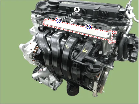
5.Remove the installation bolt (A), and then remove the delivery pipe & injector assembly from the engine.
Delivery pipe installation bolt :19.6 ~ 24.5 N.m (2.0 ~ 2.5 kgf.m, 14.5 ~ 18.1 lb-ft)
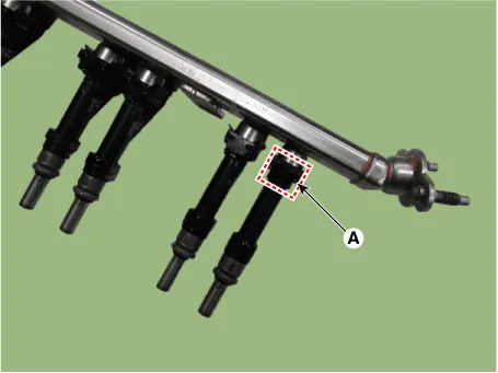
6.Remove the fixing clip (A), and then separate the injector from the delivery pipe.

ŌĆó Install the component with the specified torques.
ŌĆó Note that internal damage may occur when the component is dropped. In this case, use it after inspecting.

ŌĆó Apply the engine oil to the injector O-ring.

ŌĆó Inspect the top of the injector for debris that could damage the filter mesh.
ŌĆó Inspect the underside of the injector for bending in interference between other parts.
ŌĆó After assembling the injectors, inspect and remove any magnetic materials that may affect the magnetic circuit.
ŌĆó Inspect the injector O-ring when installing.
1.Install in the reverse order of removal.
Purge Control Solenoid Valve (PCSV)

| Item | Specification |
| Coil Resistance (Ōä”) | 12.5 ~ 16.5 [20┬░C (68┬░F)] |
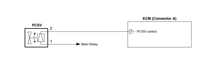

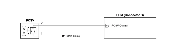

1.Turn ignition switch OFF.
2.Disconnect PCSV connector.
3.Measure resistance between PCSV terminals 1 and 2.
4.Check that the resistance is within the specification.
| Item | Specification |
| Coil Resistance (Ōä”) | 12.5 ~ 16.5 [20┬░C (68┬░F)] |
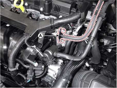
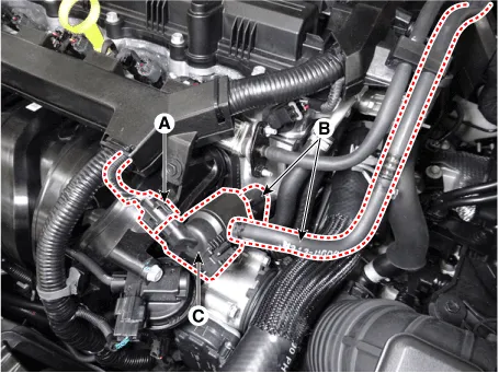
1.Turn the ignition switch OFF and disconnect the battery negative (-) cable.
2.Disconnect the purge control solenoid valve connector (A).
3.Disconnect the vapor hoses (B).
4.Remove the purge control solenoid valve (C).

ŌĆó Install the component with the specified torques.
ŌĆó Note that internal damage may occur when the component is dropped. In this case, use it after inspecting.

ŌĆó Be careful of foreign material not to flow into the valve.
1.Install in the reverse order of removal.
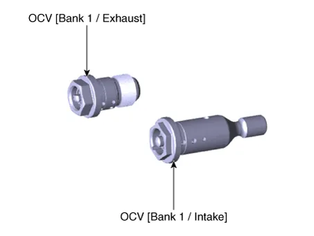
CVVT Oil Control Valve (OCV)
1.When camshaft rotates engine rotation-wise: Intake-Advance / Exhaust-Retard
2.When camshaft rotates counter engine rotation-wise: Intake- Retard / Exhaust- Advance
1.Turn ignition switch OFF.
2.Disconnect OCV connector.
3.Measure resistance between OCV terminals 1 and 2.
4.Check that the resistance is within the specification.
Specification : Refer to "Specification"
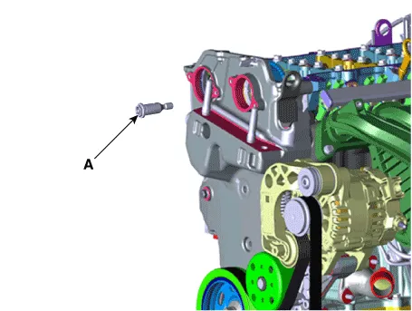
1.Turn the ignition switch OFF and disconnect the battery negative (-) cable.
2.Remove the cylinder head cover.(Refer to Engine Mechanical System - "Cylinder Head Cover")
3.When reomve the oil control valve, hold the hexagonal portion on the camshaft with a wrench to prevent the camshaft from rotating.
4.Remove the CVVT oil control valve (A).
1.Install in the reverse order of removal.
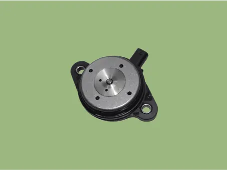
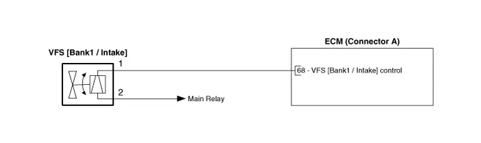
Variable Force Solenoid (VFS)
| Item | Specification |
| Coil Resistance (Ōä”) | 5.2 ~ 5.9 [20┬░C (68┬░F)] |
| Operating Voltage (V) | 10 ~ 16 |


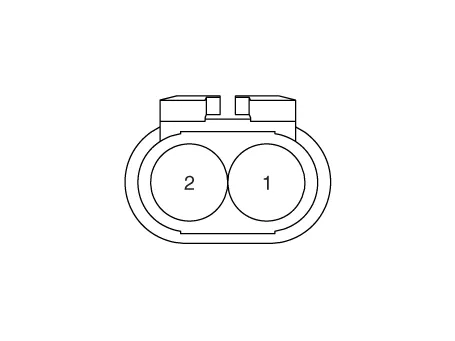
1.Turn the ignition switch OFF.
2.Disconnect the VFS connector.
3.Measure resistance between the VFS terminals 1 and 2.
4.Check that the resistance is within the specification.
| Item | Specification |
| Coil Resistance (Ōä”) | 5.2 ~ 5.9 [20┬░C (68┬░F)] |
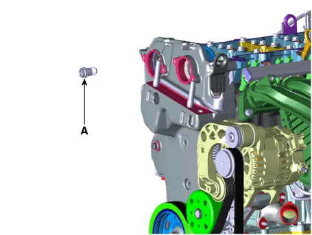
1.Turn the ignition switch OFF and disconnect the battery negative (-) cable.
2.Disconnect the variable force solenoid connector (A).
3.Remove the installation bolt (B), and then remove the variable force solenoid(VFS) from the engine.
Variable force solenoid mounting bolt :9.8 ~ 11.8 N.m (1.0 ~ 1.2 kgf.m, 7.2 ~ 8.7 lb-ft)


ŌĆó Install the component to the specified torque.
ŌĆó Note that internal damage may occur when the component is dropped. If the component has been dropped, inspect before installing.
ŌĆó Do not use any dropped variable force solenoid (VFS) valve.
ŌĆó Note below cautions when installing variable force solenoid (VFS) valve.
1)After replacing the O-ring (A) of variable force solenoid (VFS) valve, apply engine oil on new O-ring (A).
2)Push variable force solenoid (VFS) valve up to the timing chain cover, and temporarily tighten the bolt.
3)Tighten the variable force solenoid (VFS) valve to the specified torque.
1.Install in the reverse order of removal.
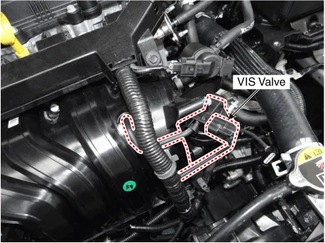
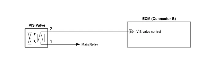
Variable Intake Solenoid (VIS) Valve

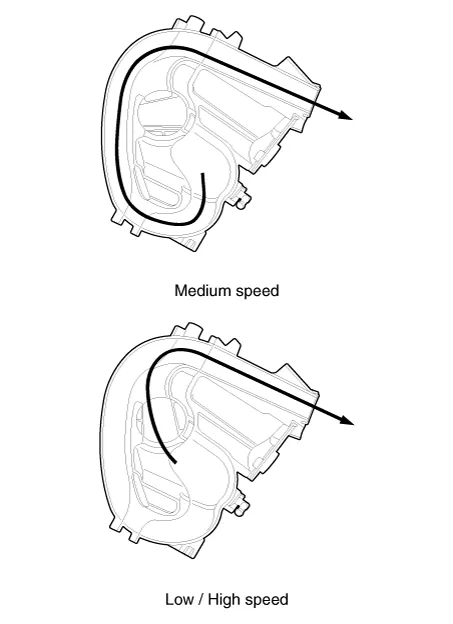
| Engine condition | VIS valve | Operation |
| Medium speed | Closed | Increasing engine performance in low engine speed by reducing intake interference among cylinders |
| Low / High speed | Open | Minimizing intake resistance by shortening intake manifold length and increasing area of air entrance |
| Item | Specification |
| Coil resistance (Ōä”) | 30.0 ~ 35.0 [20┬░C (68┬░F)] |
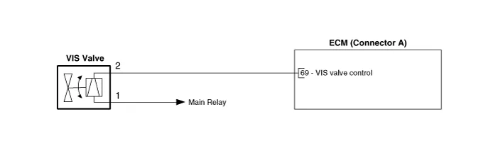
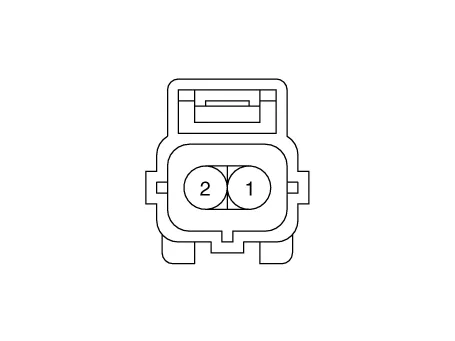

1.Turn the ignition switch OFF.
2.Disconnect the VIS valve connector.
3.Measure resistance between VIS valve terminals 1 and 2.
Specification : Refer to "Specification"
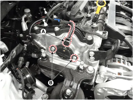
1.Turn the ignition switch OFF and disconnect the battery negative (-) cable.
2.Disconnect the VIS valve connector (A).
3.Disconnect the vacuum hoses (B) from the valve.
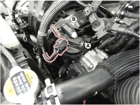
4.Remove the installation bolts, and then remove the VIS valve (A) from the surge tank.
Variable intake solenoid valve installtion bolt :9.8 ~ 11.8 N.m (1.0 ~ 1.2 kgf.m, 7.2 ~ 8.7 lb-ft)


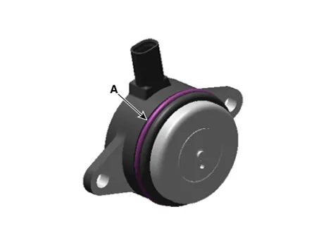
ŌĆó Install the component with the specified torques.
ŌĆó Note that internal damage may occur when the component is dropped. In this case, use it after inspecting.

ŌĆó Be careful of foreign material not to flow into the valve.
1.Install in the reverse order of removal.
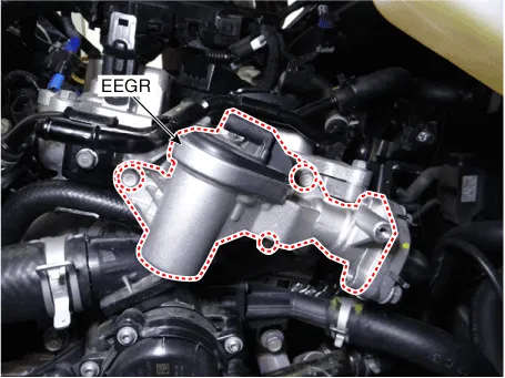
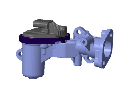
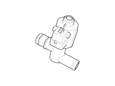
Electric EGR Control Valve
| Item | Specification |
| Coil Resistance (Ōä”) | 2.21 ~ 2.99 [20┬░C (68┬░F)] |
| Item | Specification |
| Supply Voltage (V) | 5 |
| Opened Voltage (V) | 0.7 ~ 1.25 |
| Closed Voltage (V) | 3.85 ~ 4.15 |
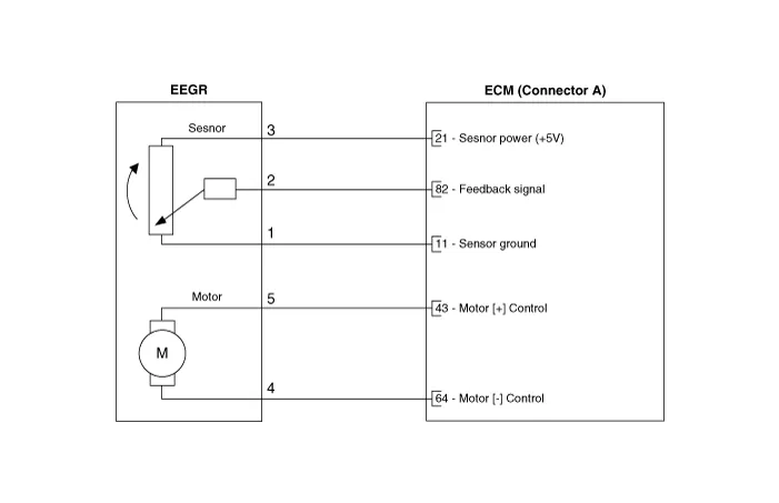


1.Turn the ignition switch OFF.
2.Disconnect the EEGR valve connector.
3.Check that the EEGR valve is stuck by foreign material.
4.Measure resistance between motor 4 and 5 control terminals of the motor.
5.Check that the resistance is within the specification.
| Item | Specification |
| Coil Resistance (Ōä”) | 2.21 ~ 2.99 [20┬░C (68┬░F)] |
1.Connect the GDS to the data link connector.
2.Perform the fully open and the fully closing operation of the EEGR valve by using the actuation test.
3.Check that the voltage is within the specification.
| Item | Specification |
| Supply Voltage (V) | 5 |
| Opened Voltage (V) | 0.7 ~ 1.25 |
| Closed Voltage (V) | 3.85 ~ 4.15 |
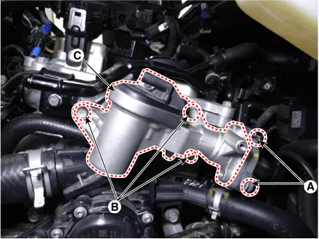
1.Turn the ignition switch OFF and disconnect the battery negative (-) terminal.
2.Remove the battery tray.(Refer to Engine Electrical System - "Battery")
3.Disconnect the harness wiring & injector connector.
4.Remove the EEGR cooler pipe (A).
5.Remove the EEGR control valve (C) after removing the mounting bolts (B).
Electric EGR cooler pipe installation bolt :18.6 ~ 23.5 N.m (1.9 ~ 2.4 kgf.m, 13.7 ~ 17.4 lb-ft)Electric EGR control valve installation bolt :12.7 ~ 14.7 N.m (1.3 ~ 1.5 kgf.m, 9.4 ~ 10.8 lb-ft)

ŌĆó Install the component with the specified torques.
ŌĆó Note that internal damage may occur when the component is dropped. In this case, use it after inspecting.

ŌĆó Be careful of foreign material not to flow into the valve.
1.Install in the reverse order of removal.
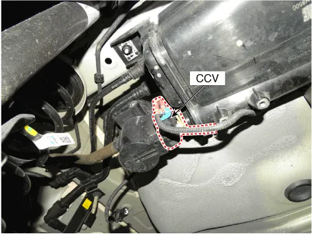
Canister Close Valve (CCV)
| Item | Specification |
| Coil Resistance (╬®) | 19.8 - 20.8 [20┬░C (68┬░F)] |
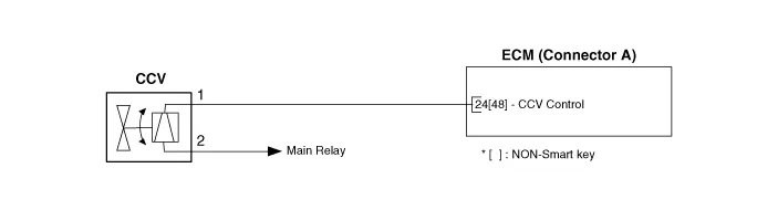

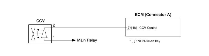
1.Turn the ignition switch OFF.
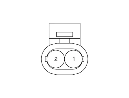
2.Disconnect the CCV connector.
3.Measure resistance between the CCV terminal 1 and 2.
4.Check that the resistance is within the specification.
Specification : Refer to "Specification"
5.Disconnect the vapor hose connected with the canister from the CCV.
6.Connect a vacuum pump to the nipple.
7.Ground the CCV control line and apply battery voltage to the CCV power supply line.
8.Apply vacuum and check the valve operation.
Specification : Vacuum maintained
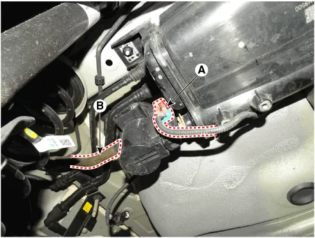
1.Turn the ignition switch OFF and disconnect the battery negative (-) cable.
2.Lift the vehicle.
3.Disconnect the canister close velve extension connector (A).
4.Remove the canister protector (B).
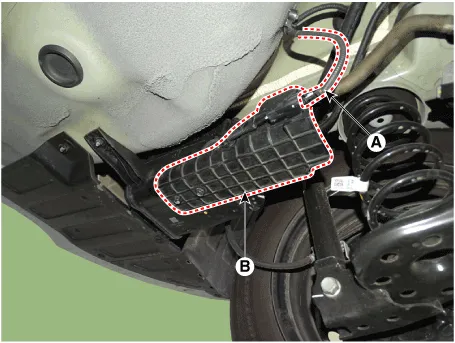
5.Disconnect the canister close velve connector (A).
6.Remove the ventilation hose (B).
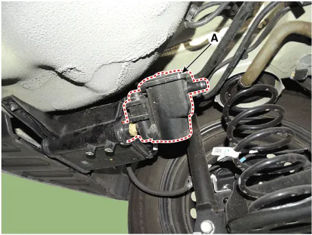
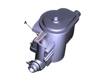
7.Remove the air filter (A).
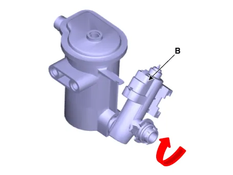
8.Release the lever (A), and then separate the canister close valve (B) from the fuel tank air filter after rotating it in the direction of the arrow in the figure.

ŌĆó Install the component with the specified torques.
ŌĆó Note that internal damage may occur when the component is dropped. In this case, use it after inspecting.
1.Install in the reverse order of removal.
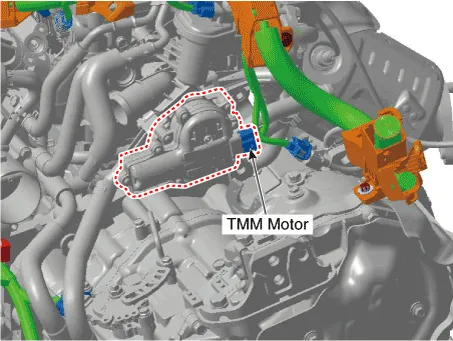
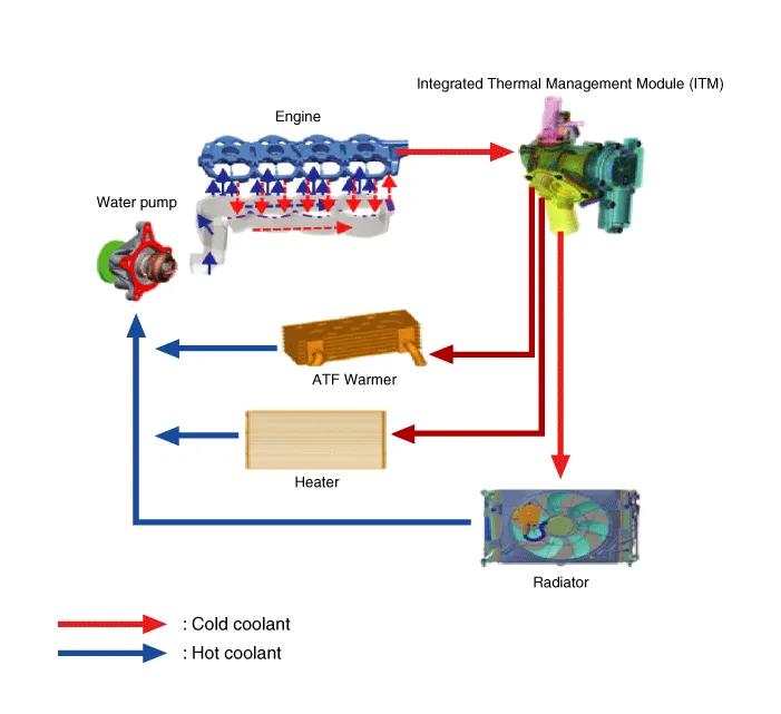
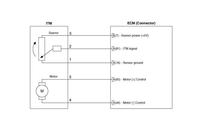
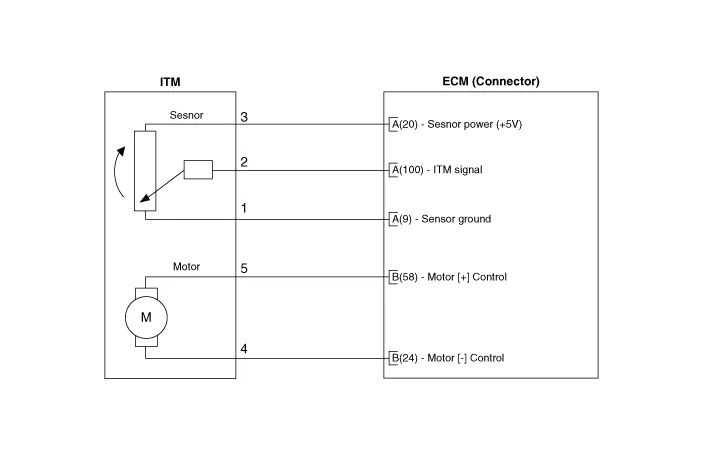
Thermal Management Module (TMM) Motor
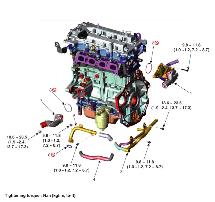
1. Integrated thermal management module (ITM)
2. Integrated thermal management module (ITM) O-ring
3. Heater pipe B
4. Heater water hose
5. Heater pipe A
6. Heater pipe A gasket
7. Water inlet fitting
8. Water inlet fitting gasket

1.Remove the integrated thermal management module (ITM).(Refer to Engine Mechanical System - "Integrated Thermal Management Module (ITM)")

ŌĆó A separate replacement of the ITM (Integrated Thermal Management Motor) is not possible. You should place the new ITM (Integrated Thermal Management Module) assembly to fix the problem.
1.Install in the reverse order of removal.

ŌĆó A separate replacement of the ITM (Integrated Thermal Management Motor) is not possible. You should place the new ITM (Integrated Thermal Management Module) assembly to fix the problem.


Other information:
Hyundai Accent (HC) (2017 - 2022) Service Manual: If You Have a Flat Tire
WARNING Changing a tire can be dangerous. Follow the instructions in this section when changing a tire to reduce the risk of serious injury or death. Whenever possible, change the tire on a firm, level surface away from traffic. CAUTION Be careful as you use the jack handle to stay clear of the flat end. The flat end has sharp edges that could cause cuts.Hyundai Accent (HC) (2017 - 2022) Service Manual: Feature of Your Audio
Head unit Ō¢Ā Type C Ō¢Ā Type D ŌØł The actual image in the Hyundai Accent may differ from the illustration. (1) POWER/VOL knob Turn to adjust the volume. Press to turn the device on or off. (2) RADIO Start FM, AM and SiriusXM* Radio. (3) MEDIA Select USB (iPod┬«), Bluetooth┬« Wireless Technology (BT) Audio, AUX or My Music. Display the media menu when two or more media are connected or when the [MEDIA] button is pressed in media mode.
Contents
- Components and Components Location
- Description and Operation
- Engine Control Module (ECM)
- Mass Air Flow Sensor (MAFS)
- ETC (Electronic Throttle control) System
- Manifold Absolute Pressure Sensor (MAPS)
- Intake Air Temperature Sensor (IATS)
- Engine Coolant Temperature Sensor (ECTS)
- Crankshaft Position Sensor (CKPS)
- Camshaft Position Sensor (CMPS)
- Knock Sensor (KS)
- Heated Oxygen Sensor (HO2S)
- Accelerator Position Sensor (APS)
- Fuel Tank Pressure Sensor (FTPS)
- Injector
- Purge Control Solenoid Valve (PCSV)
- CVVT Oil Control Valve (OCV)
- Variable Force Solenoid (VFS)
- Variable Intake Solenoid (VIS) Valve
- Electric EGR Control Valve
- Canister Close Valve (CCV)
- Thermal Management Module (TMM) Motor
Categories
- Manuals Home
- Hyundai Accent Owners Manual
- Hyundai Accent Service Manual
- Questions & Answers
- Video Guides
- Useful Resources
- New on site
- Most important about car
- Privacy Policy

0.0106