Hyundai Accent (HC): Engine Control / Fuel System
Contents:
Specifications
| Items | Specification | |
| Fuel Tank | Capacity | 43 lit. (11.4 U.S.gal., 45.4 U.S.qt., 37.8 Imp.qt.) |
| Fuel Filter (built in Fuel Pump Assembly) | Type | Paper type |
| Fuel Pressure Regulator (built in Fuel Pump assembly) | Regulated Fuel Pressure | 323 ~ 363kpa (3.29 ~ 3.70kgf/cm, 46.79 ~ 52.63 psi) |
| Fuel Pump | Type | Electrical, in-tank type |
| Driven by | Electric motor | |
| Fuel Retrun System | Type | Returnless |
Manifold Absolute Pressure Sensor (MAPS)
â–· Type : Piezo-resistive pressure sensor typeâ–· Specification| Pressure (kPa) | Output Voltage (V) |
| 10.0 | 0.5 |
| 62.5 | 2.5 |
| 115 | 4.5 |
Intake Air Temperature Sensor (IATS)
▷ Type : Thermistor type▷ Specification| Temperature [°C (°F)] | Resistance (kΩ) |
| -40 (-40) | 38.88 ~ 50.77 |
| -20 (-4) | 13.19 ~ 16.82 |
| 0 (32) | 5.11 ~ 6.11 |
| 20 (68) | 2.19 ~ 2.69 |
| 40 (104) | 1.02 ~ 1.26 |
| 60 (140) | 0.51 ~ 0.64 |
| 80 (176) | 0.27 ~ 0.35 |
Engine Coolant Temperature Sensor (ECTS)
▷ Type : Thermistor type▷ Specification| Temperature [°C (°F)] | Resistance (kΩ) |
| -40 (-40) | 41.74 ~ 54.54 |
| -30 (-22) | 23.54 ~ 29.94 |
| -20 (-4) | 14.13 ~ 16.83 |
| -10 (14) | 8.39 ~ 10.22 |
| 0 (32) | 5.28 ~ 6.29 |
| 10 (50) | 3.42 ~ 4.00 |
| 20 (68) | 2.31 ~ 2.59 |
| 30 (86) | 1.55 ~ 1.86 |
| 40 (104) | 1.08 ~ 1.21 |
| 50 (122) | 0.77 ~ 0.85 |
| 60 (140) | 0.56 ~ 0.61 |
| 70 (158) | 0.41 ~ 0.44 |
| 80 (176) | 0.31 ~ 0.33 |
| 90 (194) | 0.23 ~ 0.25 |
| 100 (212) | 0.18 ~ 0.19 |
Throttle Position Sensor (TPS)
â–· Type : Absolute Rotary Sensor ICâ–· Specification

Heated Oxygen Sensor (HO2S) [Bank 1 / Sensor 1]
▷ Type : Zirconia (ZrO2) type▷ Specification| Item | Resistance (Ω) |
| Heater Resistance (Ω) | Approx. 2.5 (20°C) |
Heated Oxygen Sensor (HO2S) [Bank 1 / Sensor 2]
▷ Type : Zirconia (ZrO2) type▷ Specification| Item | Resistance (Ω) |
| Heater Resistance (Ω) | Approx. 3.0 (20°C) |
Camshaft Position Sensor (CMPS)
â–· Type : Hall effect typeCrankshaft Position Sensor (CKPS)
â–· Type : Magnetic field sensitive TypeKnock Sensor (KS)
â–· Type : Piezo-electricity typeâ–· Specification| Item | Specification | Remarks |
| Capacitance (pF) | 850 ~ 1150 | 1 Khz |
| Insulation registance (MΩ) | 850 ~ 1150 | Pin to Body |
Accelerator Position Sensor (APS)
â–· Type : Inductiv typeâ–· Specification| Items | Specification | |
| APS 1 | APS 2 | |
| C.T | 0.7 ~ 0.8 | 0.33 ~ 0.43 |
| W.O.T | 4.13 ~ 4.22 | 2.04 ~ 2.13 |
Fuel Tank Pressure Sensor (FTPS)
▷ Type : Piezo - Resistivity type ▷ Specification| Pressure [kPa (kgf/cm², in H2O) | Output Voltage (V) |
| -6.67 (-0.068, -26.8) | 0.5 |
| 0 | 2.5 |
| +6.67 (0.068, 26.8) | 4.5 |
Injector
â–· Number : 8â–· Specification| Item | Specification |
| Coil Resistance (Ω) | 11.4 ~ 12.6 [20°C (68°F)] |
Purge Control Solenoid Valve (PCSV)
â–· Specification| Item | Specification |
| Coil Resistance (Ω) | 12.5 ~ 16.5 [20°C (68°F)] |
Variable Force Solenoid (VFS) [Bank 1/ Intake, Exhaust]
â–· Specification| Item | Specification |
| Coil Resistance (Ω) | 5.2 ~ 5.9 [20°C (68°F)] |
| Operating Voltage (V) | 10 ~ 16 |
Variable Intake Solenoid (VIS) Valve
â–· Specification| Item | Specification |
| Coil Resistance (Ω) | 30.0 ~ 35.0 [20°C (68°F)] |
ETC Motor
â–· Specification| Item | Specification |
| Coil Resistance (Ω) | 1.4 ~ 1.5 [25 ± 5°C (77 ± 41°F)] |
Canister Close Valve (CCV)
â–· Specification| Item | Specification |
| Coil Resistance (Ω) | 19.8 - 20.8 (20°C) |
| Ignition Timing | BTDC 2° ± 10° | ||
| Idle Speed | A/CON OFF | Neutral, N, P-range | 630 ± 100 |
| D-range | 630 ± 100 | ||
| A/CON ON | Neutral, N, P-range | 630 ± 100 | |
| D, R-range | 680 ± 100 | ||
Engine Control System
| Item | kgf.m | N.m | lb-ft |
| ECM installation nuts [A/T] | 1.0 ~ 1.2 | 9.8 ~ 11.8 | 7.2 ~ 8.7 |
| ECM installation screws [M/T] | 0.092 ~ 0.096 | 0.9 ~ 0.95 | 0.6 ~ 0.7 |
| ECM bracket installation bolt | 1.0 ~ 1.2 | 9.8 ~ 11.8 | 7.2 ~ 8.7 |
| ECM bracket installation nut | 1.0 ~ 1.2 | 9.8 ~ 11.8 | 7.2 ~ 8.7 |
| Manifold absolute pressure sensor installation bolt | 0.7 ~ 0.9 | 6.9 ~ 8.8 | 5.1 ~ 6.5 |
| Engine coolant temperature sensor installation | 3.0 ~ 4.0 | 29.4 ~ 39.2 | 21.7 ~ 28.9 |
| Crankshaft position sensor installation bolt | 0.8 ~ 1.2 | 7.8 ~ 11.8 | 5.8 ~ 8.7 |
| Camshaft position sensor (Bank 1 / Intake) installation bolt | 0.8 ~ 1.2 | 7.8 ~ 11.8 | 5.8 ~ 8.7 |
| Camshaft position sensor (Bank 1 / Exhaust) installation bolt | 0.8 ~ 1.2 | 7.8 ~ 11.8 | 5.8 ~ 8.7 |
| Knock sensor installation bolt | 1.9 ~ 2.5 | 18.6 ~ 24.5 | 13.7 ~ 18.1 |
| Heated oxygen sensor (Bank 1 / Sensor 1) installation | 4.0 ~ 5.0 | 39.2 ~ 49.1 | 28.9 ~ 36.2 |
| Heated oxygen sensor (Bank 1 / Sensor 2) installation | 4.0 ~ 5.0 | 39.2 ~ 49.1 | 28.9 ~ 36.2 |
| ETC (Electronic Throttle Control) module installation bolt | 1.0 ~ 1.2 | 9.8 ~ 11.8 | 7.2 ~ 8.7 |
| CVVT oil control valve (Bank 1 / Intake) installation bolt | 1.0 ~ 1.2 | 9.8 ~ 11.8 | 7.2 ~ 8.7 |
| CVVT oil control valve (Bank 1 / Exhaust) installation bolt | 1.0 ~ 1.2 | 9.8 ~ 11.8 | 7.2 ~ 8.7 |
| Ignition coil installation bolt | 1.0 ~ 1.2 | 9.8 ~ 11.8 | 7.2 ~ 8.7 |
| Variable intake solenoid valve bracket installtion bolt | 1.0 ~ 1.2 | 9.8 ~ 11.8 | 7.2 ~ 8.7 |
Fuel Delivery System
| Item | kgf.m | N.m | lb-ft |
| Fuel tank installation nut | 4.0 ~ 5.5 | 39.2 ~ 53.9 | 28.9 ~ 39.8 |
| Fuel pump plate cover installation bolt | 0.2 ~ 0.3 | 2.0 ~ 2.9 | 1.4 ~ 2.2 |
| Filler-neck assembly installation bolt | 0.8 ~ 1.2 | 7.8 ~ 11.8 | 5.8 ~ 8.7 |
| Filler-neck assembly installation screw | 0.8 ~ 1.2 | 7.8 ~ 11.8 | 5.8 ~ 8.7 |
| Delivery pipe installation bolt | 2.0 ~ 2.5 | 19.6 ~ 24.5 | 14.5 ~ 18.1 |
| Delivery pipe installation nut (↔ Fuel feed tube) | 0.4 ~ 0.6 | 3.9 ~ 5.9 | 2.9 ~ 4.3 |
| Accelerator pedal installation nut | 1.3 ~ 1.6 | 12.7 ~ 15.7 | 9.4 ~ 11.6 |
| Accelerator pedal installation bolt | 0.9 ~ 1.4 | 8.8 ~ 13.7 | 6.5 ~ 10.1 |
Special Service Tools
| Tool (Number and name) | Illustration | Application |
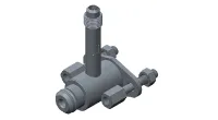
| 09353-24100 Fuel Pressure Gauge |
| Measuring the fuel line pressure |
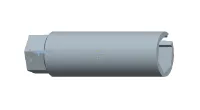
| 09353-38000 Fuel Pressure Gauge Adapter |
| Connection between the delivery pipe and fuel feed line |
| 09353-24000 Fuel Pressure Gauge Connector |
| Connection between Fuel Pressure Gauge (09353-24100) and Fuel Pressure Gauge Adapter (09353-38000) |
| 09392-1Y100 Heated Oxygen Sensor Socket Wrench |
| Removal and installation of the heated oxygen sensor ※ SST No. 09392-2H100 model also can be used for removing the heated oxygen sensor. |
| 09310-F3100 Fuel Pump Plate Cover Wrench |
| Removing and installation fuel pump plate cover |


Troubleshooting ➤
Engine Control System ➤
Fuel Delivery System ➤


Other information:
Hyundai Accent (HC) (2017 - 2022) Service Manual: Description and Operation
- Description System Overview The System offers the following features: – Human machine interface through a 1-stage button, for terminal switching and engine start. – Control of external relays for ACC / IGN1 / IGN2 terminal switching and STARTER, without use of mechanical ignition switch. – Steering column locking with an ESCL device; Monitoring of the vehicle status to insure safe activation of the ESCL.Information - Using Bluetooth® Wireless Technology(BT) Cellular Phone Bluetooth® Wireless Technology is a near-field wireless networking technology that uses the 2.4 GHz frequency to connect various devices within a certain distance wirelessly. In the Hyundai Accent, Bluetooth® Wireless Technology supports handsfree calling and (when compatible) media streaming.
Contents
Categories
- Manuals Home
- Hyundai Accent Owners Manual
- Hyundai Accent Service Manual
- Questions & Answers
- Video Guides
- Useful Resources
- New on site
- Most important about car
- Privacy Policy

0.008