Hyundai Accent (HC): Engine Control / Fuel System / Fuel Delivery System
Contents:
- Components and Components Location
- Fuel Pressure Test
- Release Residual Pressure in Fuel Line
- Fuel Tank
- Fuel Pump
- Fuel Filter
- Fuel Pump Motor
- Fuel Sensor
- Fuel Pressure Regulator
- Fuel Line
- Filler-Neck Assembly
- Accelerator Pedal
- Delivery Pipe
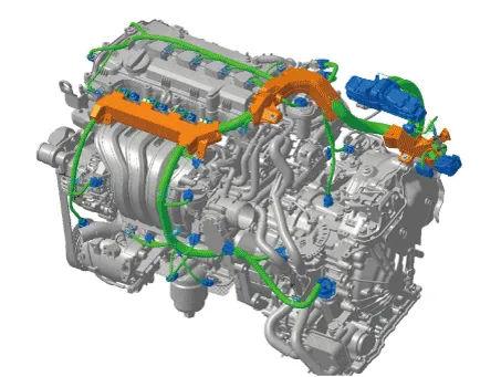
Components and Components Location
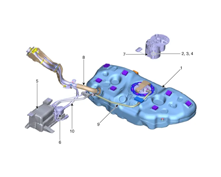
1. Fuel tank
2. Fuel pump
3. Fuel filter
4. Fuel pressure regulator
5. Canister
6. Fuel tank air filter
7. Fuel level sensor (FLS)
8. Fuel filler hose
9. Vapor tube
10. Ventilation tube
Fuel Pressure Test
1.Release the residual pressure in fuel line.(Refer to Fuel Delivery System - "Release Residual Pressure in Fuel Line")

• When removing the fuel pump fuse, a Diagnostic Trouble Code (DTC) may occur. Delete the code with the GDS after completion of "Release Residual Pressure in Fuel Line" work.
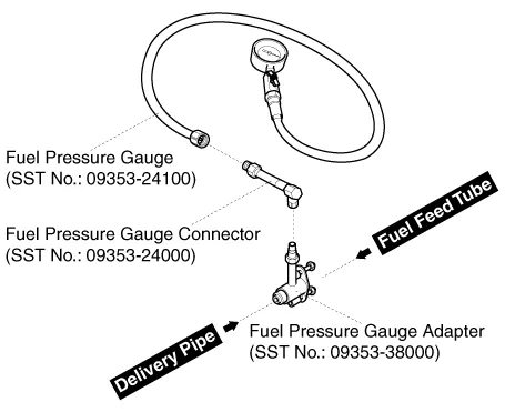
2.Install the Special Service Tool (SST).
(1)Disconnect the fuel feed tube from the delivery pipe.

• There may be some residual pressure even after “Release Residual Pressure in Fuel Line” work, so cover the hose connection with a shop towel to prevent residual fuel from spilling out before disconnecting any fuel connection.
(2)Install the special service tool for measuring the fuel pressure in between the fuel feed tube and the fuel delivery pipe (Refer to the figure below).
3. Inspect fuel leakage on connections among the fuel feed tube, the delivery pipe, and the SST components with IG ON.
4. Measure Fuel Pressure.
(1)Start the engine and measure the fuel pressure at idle.
Fuel Pressure : 323 ~ 363 kPa (3.3 ~ 3.7 kgf/cm², 46.8 ~ 52.6 psi)

• If the fuel pressure differs from the standard value, repair or replace the related part (Refer to the table below).
| Fuel Pressure | Cause | Related Part |
| Too Low | Fuel filter clogged | Fuel Filter |
| Fuel leakage | Fuel Pressure Regulator | |
| Too High | Fuel pressure regulator valve stuck | Fuel Pressure Regulator |
(2)Stop the engine, and then check for the change in the fuel pressure gauge reading.
Standard Value : The gauge reading should hold for about 5 minutes after the engine stops

• If the gauge reading should not be held, repair or replace the related part (Refer to the table below).
| Fuel Pressure (After Engine Stops) | Cause | Related Part |
| Fuel Pressure Drops Slowly | Leakage on injector | Injector |
| Fuel Pressure Drops Immediately | Check valve of fuel pump stuck open | Fuel Pump |
(3)Turn the ignition switch OFF.
5.Release the residual pressure in fuel line.(Refer to Fuel Delivery System - "Release Residual Pressure in Fuel Line")

• When removing the fuel pump fuse, a Diagnostic Trouble Code (DTC) may occur. Delete the code with the GDS after completion of "Release Residual Pressure in Fuel Line" work.
6.Test End
(1)Remove the Special Service Tool (SST) from the fuel feed tube and the delivery pipe.
(2)Connect the fuel feed tube and the delivery pipe.
Release Residual Pressure in Fuel Line

• There may be some residual pressure even after "Release Residual Pressure in Fuel Line" work, so cover the hose connection with a shop towel to prevent residual fuel from spilling out before disconnecting any fuel connection.
1.Turn the ignition switch OFF and disconnect the battery (-) cable.
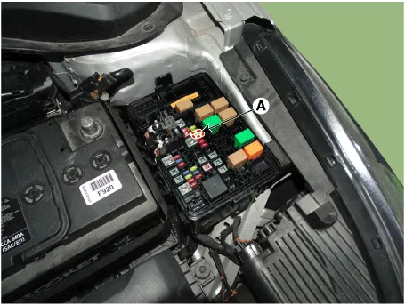
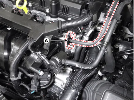
2.Remove the fuel pump fuse (A).
3.Connect the battery (-) cable.
4.Start the engine and let idle, and then turn the ignition switch OFF after the engine has stopped on its own.
5.Disconnect the battery (-) cable, and then install the fuel pump fuse.
6.Connect the battery (-) cable.
7.Delete the Diagnostic Trouble Code (DTC) related the fuel pump fuse with the GDS.

• When removing the fuel pump fuse, a Diagnostic Trouble Code (DTC) may occur. Delete the code with the GDS after completion of "Release Residual Pressure in Fuel Line" work.
Fuel Tank
1.Release the residual pressure in fuel line.(Refer to Fuel Delivery System - "Release Residual Pressure in Fuel Line")
2.Remove the rear seat.(Refer to Body - "Rear Seat Assembly")
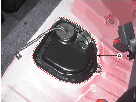
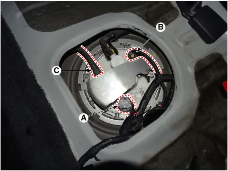
3.Remove the fuel pump service cover (A).
4. Disconnect the fuel pump connector (A).
5.Disconnect the fuel tank pressure sensor connector (B).
6.Disconnect the fuel feed tube quick connector (C).
7.Lift the vehicle.
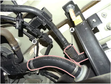
8.Disconnect the vapor tube quick connector (A).
9.Disconnect the fuel filler hose (B).
10.Remove the side under cover (A).
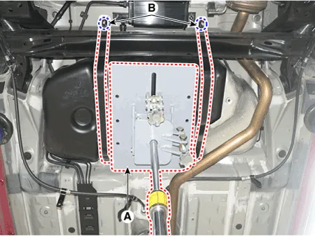
11.Remove the brake line (A) bracket mounting bolts (B).
12.Support the fuel tank with jack (A).
13.Remove the fuel tank installation nut (B) and then loosen the fuel tank.
Fuel tank band installation nut :39.2 - 54.0 N.m (4.0 - 5.5 kgf.m, 28.9 - 39.8 lb-ft)
1.Install in the reverse order of removal.
Fuel Pump
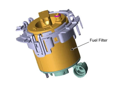
Fuel Filter
1.Remove the fuel pump. (Refer to Fuel Delivery System - "Fuel Pump")
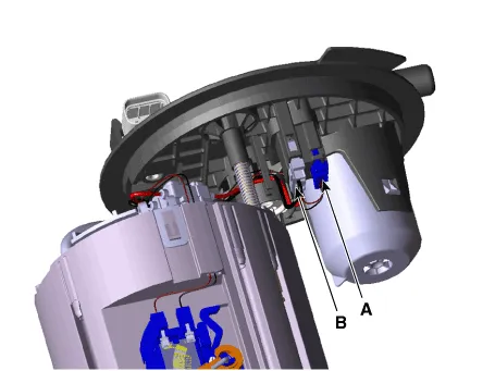
2.Disconnect the electric pump wiring connector (A) and the fuel sender connector (B).
3.Remove the head assembly (A) after releasing the cushion fixing hooks.
4.Disconnect the fuel tube quick-connectors (B).

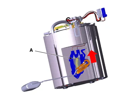
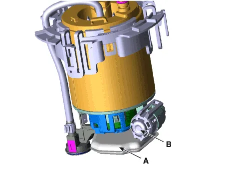
5.Remove the fuel sender (A) in the direction of an arrow.
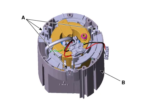
6.Remove the reservior-cup (B) after releasing the fixing hooks (A).
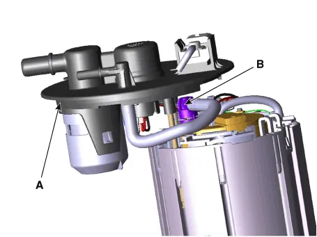
7.Disconnect the ground (A).
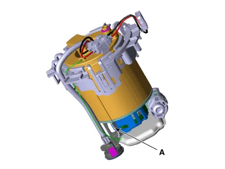
8.Release the fixing hooks, and then remove the pre-filter (A) and the fuel pressure regulator (B).
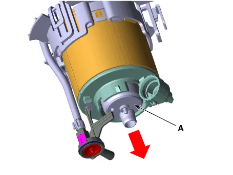
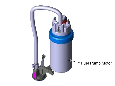
9.Remove the fuel pump motor (A) in the direvtion ofan arrow.


• Be careful of O-ring.
1.Installation is reverse of removal.
Fuel Pump Motor
1.Remove the fuel pump. (Refer to Fuel Delivery System - "Fuel Pump")
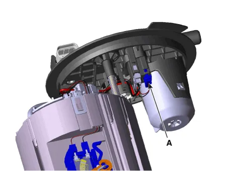
2.Disconnect the electric pump wiring connector (A) and the fuel sender connector (B).

3.Remove the head assembly (A) after releasing the cushion fixing hooks.
4.Disconnect the fuel tube quick-connectors (B).

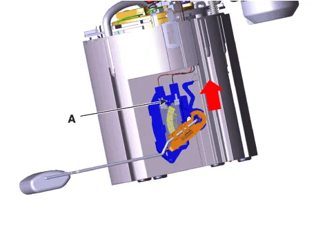
5.Remove the fuel sender (A) in the direction of an arrow.

6.Remove the reservior-cup (B) after releasing the fixing hooks (A).

7.Disconnect the ground (A).

8.Release the fixing hooks, and then remove the pre-filter (A) and the fuel pressure regulator (B).

9.Remove the fuel pump motor (A) in the direvtion of an arrow.
1.Installation is reverse of removal.
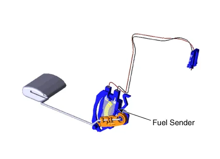
Fuel Sensor
1. Remove the fuel pump.(Refer to Fuel Delivery System - "Fuel Pump")
2.Disconnect the fuel sender connector (A).
3.Remove the fuel sender (A) in the direction of an arrow.
1.Installation is reverse of removal.
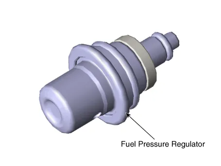
Fuel Pressure Regulator
1.Remove the fuel pump. (Refer to Fuel Delivery System - "Fuel Pump")
2.Disconnect the electric pump wiring connector (A) and the fuel sender connector (B).

3.Remove the head assembly (A) after releasing the cushion fixing hooks.
4.Disconnect the fuel tube quick-connectors (B).
5.Remove the fuel sender (A) in the direction of an arrow.

6.Remove the reservior-cup (B) after releasing the fixing hooks (A).

7.Release the fixing hooks, and then remove the fuel pressure regulator (A).

1.Installation is reverse of removal.
Fuel Line
1. Turn the ignition switch OFF, and then remove battery (-) cable.
2.Release the residual pressure in fuel line. (Refer to Fuel Delivery System - "Release Residual Pressure in Fuel Line")
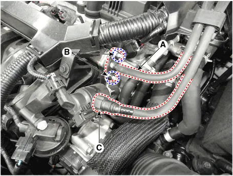
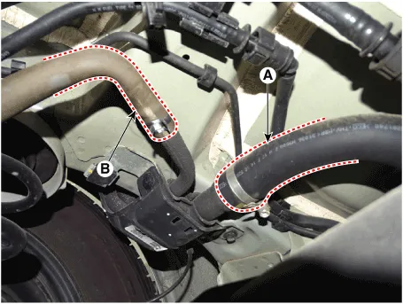
3.Disconnect the fuel feed tube (A) after remove the nuts (B).
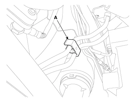
4.Disconnect the vapor tube quick-connector (C) which is connected from the PCSV.
5. Lift the vehicle.
6.Remove the fuel tank. (Refer to Fuel Delivery System - "Fuel Tank")
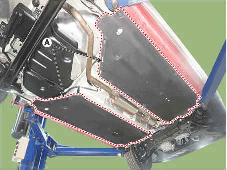
7.Disconnect the fuel & brake line protect (A) from the fixing clip.
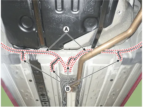
8.Remove the fuel line fixing clip (A).
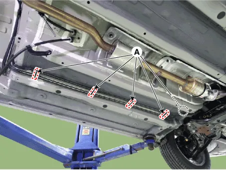
9.Remove the fuel line fixing clip (A).
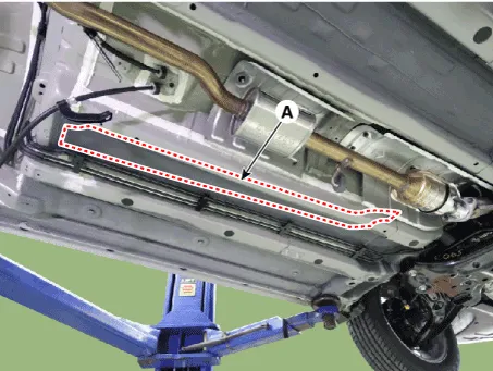
10.Remove the fuel line (A).
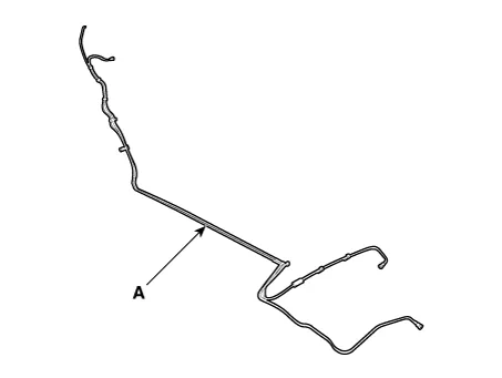
1.Install in the reverse order of removal.
Filler-Neck Assembly
1.Remove the rear-LH wheel, tire, and the inner wheel house.
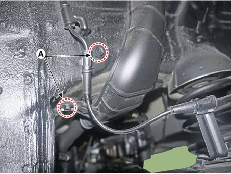
2.Disconnect the fuel filler hose (A).
3.Disconnect the ventilation hose (B) and leveling hose (C).
4.Open the fuel filler door and unfasten the filler-neck assembly mounting screw (A).
Filler-neck assembly bracket installation screw : 3.9 ~ 5.9 N.m (0.4 ~ 0.6 kgf.m, 2.9 ~ 4.3 lb-ft)
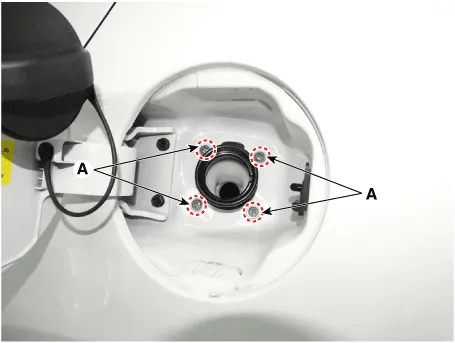
5.Remove the filler-neck assembly from the vehicle after removing the bracket mounting bolts (A).
Filler-neck assembly installation bolt :7.8 ~ 11.8 N.m (0.8 ~ 1.2 kgf.m, 5.8 ~ 8.7 lb-ft)
1. Install in the reverse order of removal.
Accelerator Pedal
1.Turn the ignition switch OFF and disconnect the negative (-) battery cable.
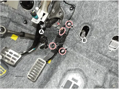
2.Disconnect the accelerator position sensor connector (A).
3.Remove the installation nuts (B), and then remove the accelerator pedal module.
Accelerator pedal module installation nut :12.7 - 15.7 N.m (1.3 - 1.6 kgf.m, 9.4 - 11.6 lb-ft)
1.Install in the reverse order of removal.
Delivery Pipe

• In case of removing the high pressure fuel pump, high pressure fuel pipe, delivery pipe, and injector, there may be injury caused by leakage of the high pressure fuel. So don't do any repair work right after engine stops.
1.Turn the ignition switch OFF and disconnect the battery negative (-) cable.
2.Release the residual pressure in fuel line.(Refer to Fuel Delivery System - "Release Residual Pressure in Fuel Line")
3.Disconnect the harness wiring & injector connector.
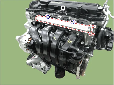
4.Remove the installation nut, and then disconnect the fuel feed tube (A).
Delivery pipe installation nut (↔ Fuel feed tube) :9.8 - 11.8 N.m (1.0 - 1.2 kgf.m, 7.2 - 8.7 lb-ft)
5.Remove the installation bolt (A), and then remove the delivery pipe & injector assembly from the engine.
Delivery pipe installation bolt :19.6 ~ 24.5 N.m (2.0 ~ 2.5 kgf.m, 14.5 ~ 18.1 lb-ft)
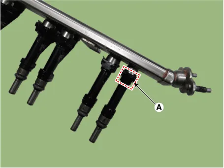
6.Remove the fixing clip (A), and then separate the injector from the delivery pipe.
1.Install in the reverse order of removal.


Other information:
Hyundai Accent (HC) (2017 - 2022) Service Manual: Stop Lamp Switch
- Components 1. Brake pedal member assembly2. Stop lamp switch3. Brake pedal arm 4. Pedal pad - Schematic Diagram - System circuit diagram - Terminal function TerminalDescription 1IGN 2BS 3- 4B+ 5BLS 6GND - Adjustment 1.Turn ignition switch OFF and disconnect the negative (-) battery cable. 2.Remove the lower crash pad.
Contents
- Components and Components Location
- Fuel Pressure Test
- Release Residual Pressure in Fuel Line
- Fuel Tank
- Fuel Pump
- Fuel Filter
- Fuel Pump Motor
- Fuel Sensor
- Fuel Pressure Regulator
- Fuel Line
- Filler-Neck Assembly
- Accelerator Pedal
- Delivery Pipe
Categories
- Manuals Home
- Hyundai Accent Owners Manual
- Hyundai Accent Service Manual
- Questions & Answers
- Video Guides
- Useful Resources
- New on site
- Most important about car
- Privacy Policy

0.0109