Hyundai Accent (HC): Intelligent Variable Transmission (IVT) System (Continuously Variable Transmission) / Intelligent Variable Transmission (IVT)
Contents:
Components and Components Location
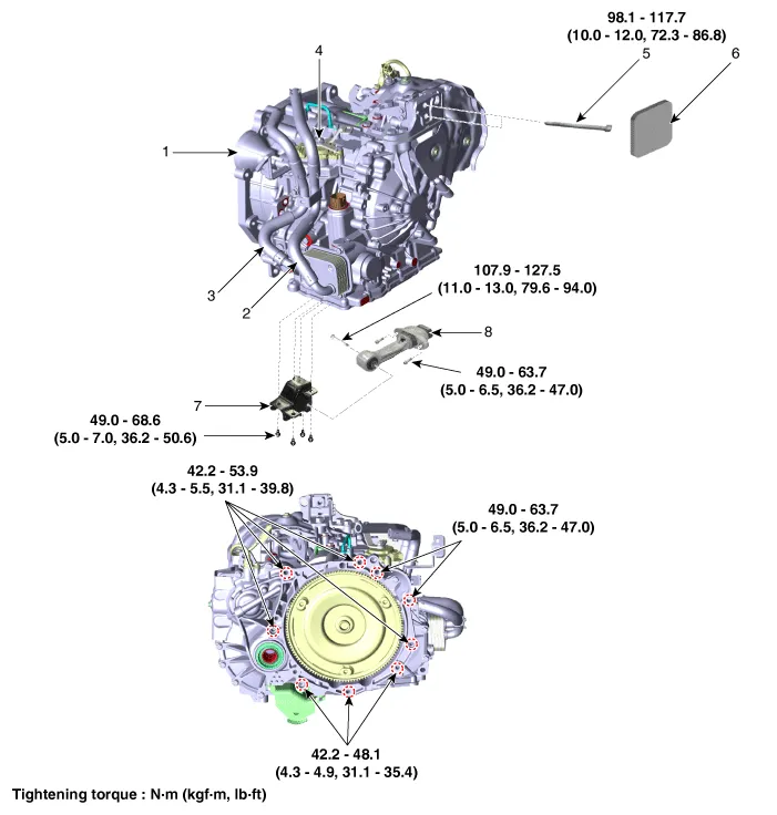
1. Intelligent variable transmission (IVT)
2. Coolant hose (IN)
3. Coolant hose (OUT)
4. Position switch
5. IVT support bracket mounting bolt
6. Cover
7. Roll rod support bracket
8. Roll rod bracket
Description and Operation
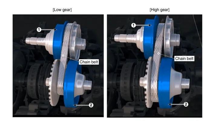
1. Driven Pulley (Output)
2. Drive Pulley (Input)
Repair procedures ➤
Oil Pan
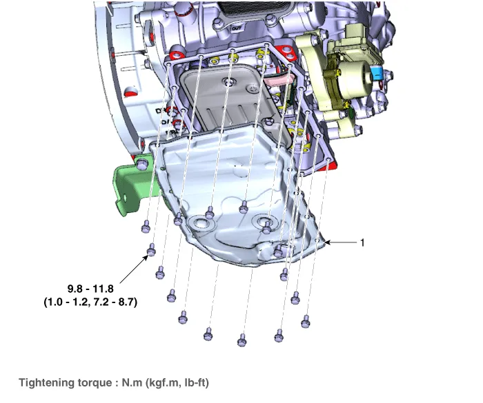
1. Oil pan
1.Remove the engine room under cover.(Refer to Engine Mechanical System - "Engine Room Under Cover")
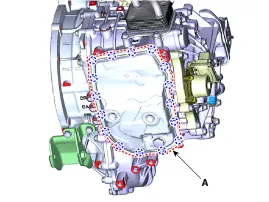
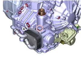
2.Remove the IVTF drain plug (A), allow the fluid to drain out and then reinstall the drain plug.
Tightening torque :34.3 - 44.1 N·m (3.5 - 4.5 kgf·m, 25.3 - 32.5 lb-ft)
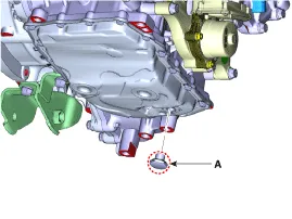

• Do not resuse gasket (A).
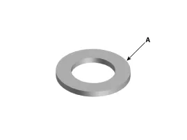
3.Remove the oil pan (A) after loosening the mounting bolts.

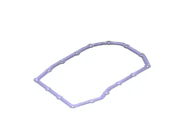
• Do not reuse the oil pan gasket.
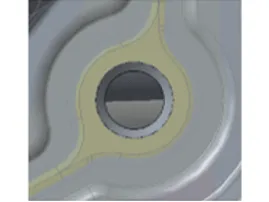
• When installing the oil pan install after visually matching the case/gasket/oil pan holes of the two standard holes (A).
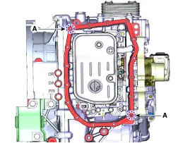
| Hole match: Assembly possible | Hole inconsistency: Oil leakage when assembled |
|
|

1.Install the oil pan (A).
Tightening torque :9.8 - 11.8 N·m (1.0 - 1.2 kgf·m, 7.2 - 8.7 lb-ft)

2.Loosen the injection plug (A) and supply IVTF.
Recommended rating : SP-CVT1Recommended oil : MICHANG SP-CVT1Oil quantity : 6.5 L (1.71 U.S.gal., 6.86 U.S.qt., 5.71 lmp.qt.)
3.Install the IVTF injection plug.
Tightening torque :34.3 - 44.1 N.m (3.5 - 4.5 kgf.m, 25.3 - 32.5 lb-ft)
4.Perform the IVTF level check procedure.(Refer to Hydraulic System - "Fluid")


Other information:
Hyundai Accent (HC) (2017 - 2022) Service Manual: Tire Replacement
On the Hyundai Accent, a tire that wears evenly will eventually reveal the built-in tread wear indicators. These indicators appear as a solid, continuous band across the tread and confirm there is less than 2/32 inch (1.6 mm) of usable tread remaining. Replace the tire when this happens to help maintain safe braking performance, stable steering control, and reliable wet-weather traction.Hyundai Accent (HC) (2017 - 2022) Service Manual: Owner maintenance
WARNING Performing maintenance work on a vehicle can be dangerous. If you lack sufficient knowledge and experience or the proper tools and equipment to do the work, have it done by an authorized HYUNDAI dealer. ALWAYS follow these precautions for performing maintenance work: Park your vehicle on level ground, move the shift lever into the P (Park, for intelligent variable transmission vehicle) position or neutral (for manual transmission vehicle), apply the parking brake, place the ignition switch in the LOCK/OFF position.
Contents
Categories
- Manuals Home
- Hyundai Accent Owners Manual
- Hyundai Accent Service Manual
- Questions & Answers
- Video Guides
- Useful Resources
- New on site
- Most important about car
- Privacy Policy

0.0051