Hyundai Accent (HC): Intelligent Variable Transmission (IVT) / Repair procedures
1.Remove the air cleaner assembly.(Refer to Engine Mechanical System - "Air cleaner")
2.Remove the battery and battery tray.(Refer to Body Electrical System - "Battery")
3.Drain the coolant.(Refer to Engine Mechanical System - "Coolant")
4.Disconnect the position switch connector (A).
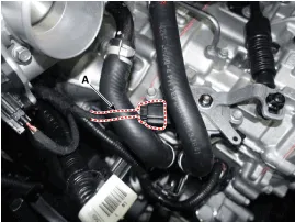
5.Disconnect the driven pully speed sensor connector (B).
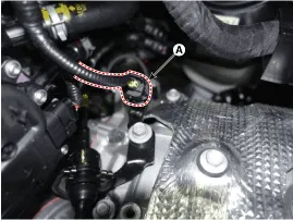
6.Loosen the nut (A), bolts (B) and then removing the shift cable (C).
Tightening torque :(A) : 9.8 - 13.7 N·m (1.0 - 1.4 kgf·m, 7.2 - 10.1 lb-ft)(B) : 14.7 - 21.6 N·m (1.5 - 2.2 kgf·m, 10.9 - 15.9 lb-ft)
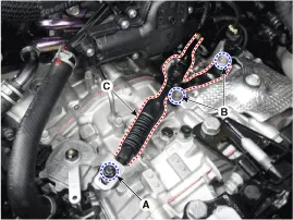
7.Remove the ground line after removing the bolt (A).
Tightening torque : 26.5 - 32.4 N·m (2.7 - 3.3 kgf·m, 19.5 - 23.9 lb-ft)
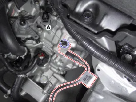
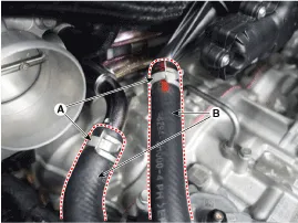
8.Separate the hose (B) after removing the Intelligent Variable Transmission Fluid(IVTF) cooler hose clamp (A).
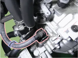
9.Disconnect the main connector (A).

• After detaching the main connector, wrap a plastic bag around the connector to prevent coolant from getting into it.
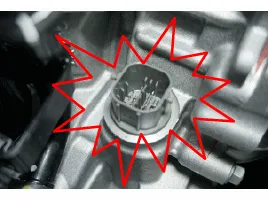
• If coolant gets into the connector, corrosion may occur inside the connector, thus causing an open/short circuit. In this case, trouble codes and shift failure may also occur.
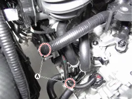
10.Separate the fixing clip (A) of wiring.
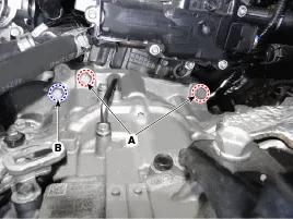
11.Remove the transmission upper mounting bolts (A) and the starter mounting bolt (B).
Tightening torque :(A) : 42.2 - 53.9 N·m (4.3 - 5.5 kgf·m, 31.1 - 39.8 lb-ft)(B) : 49.0 - 63.7 N·m (5.0 - 6.5 kgf·m, 36.2 - 47.0 lb-ft)
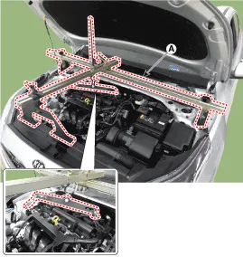
12.Assemble the engine support fixture on the engine room.(Refer to Special Service Tools - "Engine support fixture assembly drawing")
13.Using the engine support fixture (A), hold the engine and transmission assembly safely.
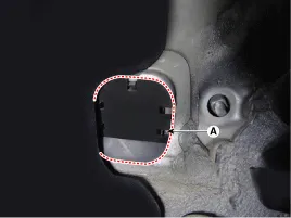
14.Remove the dust cover (A).
15.Remove the Intelligent Variable Transmission(IVT) support bracket mounting bolts (A).
Tightening torque :98.1 - 117.7 N.m (10.0 - 12.0 kgf.m, 72.3 - 86.8 lb-ft)
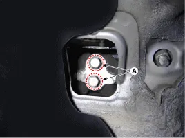
16.Remove the IVT support bracket (A).
Tightening torque :58.8 - 78.5 N·m (6.0 - 8.0 kgf·m, 43.4 - 57.9 lb-ft)
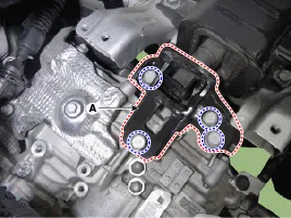
17.Remove the under cover.(Refer to Engine Mechanical System - "Engine Room Under Cover")
18.Remove the drive shaft assembly. (Refer to Driveshaft and Axle - "Front Driveshaft")
19.Remove the wiring mounting bolt (A).
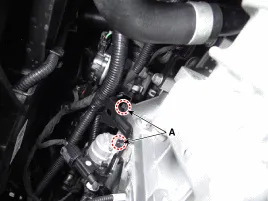
20.Remove the exhaust manifold stay (A).
Tightening torque :39.2 - 49.0 N·m (4.0 - 5.0 kgf·m, 28.9 - 36.2 lb-ft)
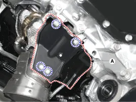
21.Remove the roll rod bracket (C) after removing the bolt (A) and (B).
Tightening torque :Bolt (A) : 107.9 - 127.5 N.m (11.0 - 13.0 kgf.m, 79.6 - 94.0 lb-ft)Bolt (B) : 49.0 - 63.7 N.m (5.0 - 6.5 kgf.m, 36.2 - 47.0 lb-ft)
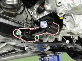
22.Remove the roll rod support bracket (D).
Tightening torque :49.0 - 68.6 N.m (5.0 - 7.0 kgf.m, 36.2 - 50.6 lb-ft)
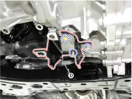
23.Remove the cover (A).
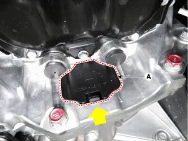

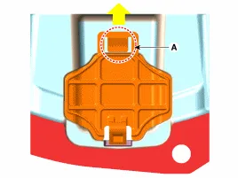
• When installing the cover, attach the fixing hook (A) so that it is inserted inside.
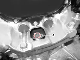
24.Remove the torque converter mounting bolts (A) by rotating the crankshaft.
Tightening torque :45.1 - 52.0 N.m (4.6 - 5.3 kgf.m, 33.3 - 38.3 lb-ft)
25.Support the transmission safely on a jack.
26.Remove the starter mounting bolt (A) and transmission lower mounting bolts (B, C).
Tightening torque :(A) : 49.0 - 63.7 N.m (5.0 - 6.5 kgf.m, 36.2 - 47.0 lb-ft) (B) : 42.2 - 48.1 N.m (4.3 - 4.9 kgf.m, 31.1 - 35.4 lb-ft)(C) : 42.2 - 53.9 N.m (4.3 - 5.5 kgf.m, 31.1 - 39.8 lb-ft)
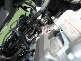
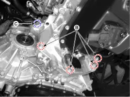
27.After separating the transmission from the engine, remove the transmission by lowering the jack slowly.

• Be careful not to damage other nearby systems or parts when removing the transmission assembly.
1.To install, reverse the removal procedures.

1)Check that there is no gap (A) between the torque converter housing (B) and the engine block (C).
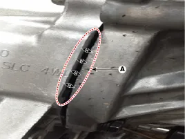
2)If a gap is visible, it means that the oil pump gear key is not
assembled properly to the torque converter hub. In this case, remove the
Intelligent Variable Transmission(IVT) and then reinstall the torque
converter to IVT according to the key shape of oil pump gear.
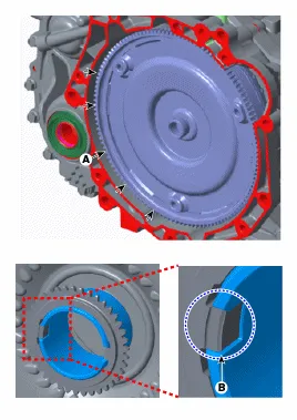
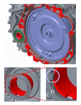
3)Incorrect mounting of the oil pump gear key can lead to damage or can break if mounting bolts are tightened by force. In this case, replace the IVT.

• Follow the procedure as shown below based on reinstallation or replacement with a new intelligent variable transmission.
2.In case of the reinstallation.
(1)If the differential oil seal is damaged and fluid is leaking, replace the oil seal with a new one. When installing a new oil seal, use the SSTs (09452-26100, 09231-H1100).
(2)Check the Intelligent Variable Transmission Fluid(IVTF) level after refilling the intelligent variable transmission with fluid. (Refer to Intelligent Variable Transmission (IVT) System - "Fluid")
(3)Injection the coolant.(Refer to Engine Mechanical System - "Coolant")
(4)Clear the diagnostic trouble codes (DTC) using the diagnostic tool. Disconnecting the battery negative terminal will not clear the DTCs. Clear DTCs using the diagnostic tool at all times.

• Even though disconnecting the battery negative terminal, the DTCs will not be cleared. So, be sure to clear the DTCs using the diagnostic tool.
3.In case of the replacing with a new IVT.
(1)Intelligent variable transmission is already filled with the specified amount of IVTF. For this reason, it is not necessary to refill and check the IVTF. However, the remaining IVTF in the IVTF cooler has to be drained.
(2)Injection the coolant.(Refer to Engine Mechanical System - "Coolant")
(3)Clear the diagnostic trouble codes (DTC) using the diagnostic tool. Disconnecting the battery negative terminal will not clear the DTCs. Clear DTCs using the diagnostic tool at all times.

• Even though disconnecting the battery negative terminal, the DTCs will not be cleared. So, be sure to clear the DTCs using the diagnostic tool.
(4)Reset the intelligent variable transmission adaptive values using the diagnostic tool.
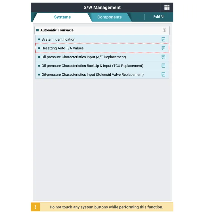
(5)Perform the hydraulic characteristics input procedure using the diagnostic tool.
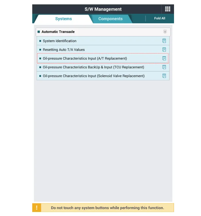
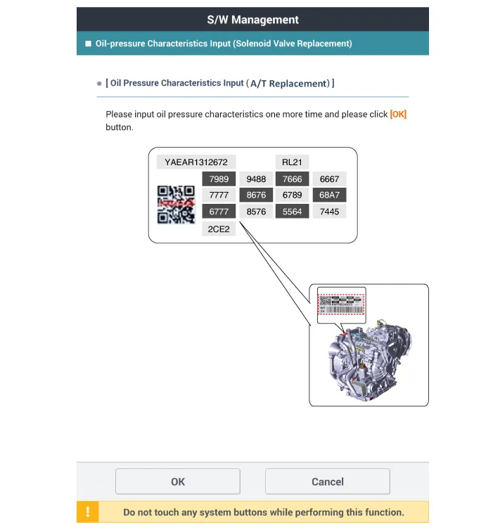
(6)Perform the TCM adaptive values learning procedure. (Refer to IVT Control System - "Repair procedures")
Other information:
Hyundai Accent (HC) (2017 - 2022) Service Manual: Automatic climate control system
1. Temperature control knob 2. Fan speed control knob 3. AUTO (automatic control) button 4. Air intake control button 5. OFF button 6. Front windshield defrost button 7. Rear window defrost button 8. Mode selection button 9. Air conditioning button 10. Climate control information screenHyundai Accent (HC) (2017 - 2022) Service Manual: Piston and Connecting Rod
- Disassembly • Use fender covers to avoid damaging painted surfaces. • To avoid damage, unplug the wiring connectors carefully while holding the connector portion. • Mark all wiring connector and hoses to avoid misconnection. • To release the fuel system pressure before removing the engine assembly, start the engine without fuel pump relay.
Categories
- Manuals Home
- Hyundai Accent Owners Manual
- Hyundai Accent Service Manual
- Questions & Answers
- Video Guides
- Useful Resources
- New on site
- Most important about car
- Privacy Policy
0.0088


