Hyundai Accent (HC): Body (Interior and Exterior) / Rear Bumper
Contents:
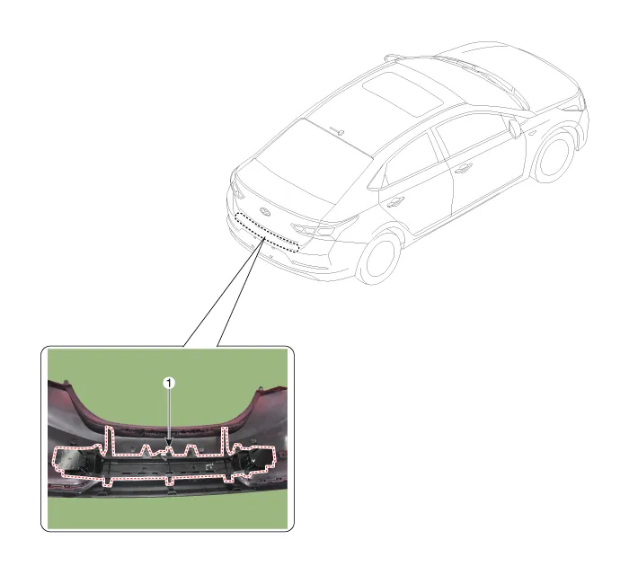
Components and Components Location
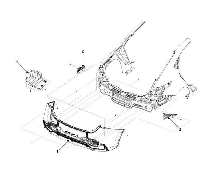
1. Rear bumper assembly
2. Rear bumper side bracket [LH]
3. Rear bumper side bracket [RH]
4. Rear bumper under cover assembly
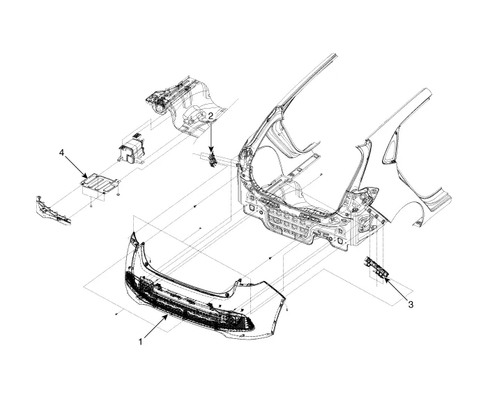
1. Rear bumper assembly
2. Rear bumper side bracket [LH]
3. Rear bumper side bracket [RH]
4. Rear bumper under cover assembly
Rear Bumper Assembly
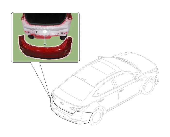
1. Rear bumper assembly

• Put on gloves to prevent hand injuries.

• When removing with a flat - tip screwdriver or remover, wrap protective tape around the tools to prevent damage to components.
• When removing the interior trim pieces, use a plastic panel removal tool not to damage the surface.
• Take care not to bend or scratch the trim and panels.
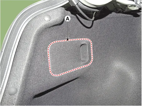
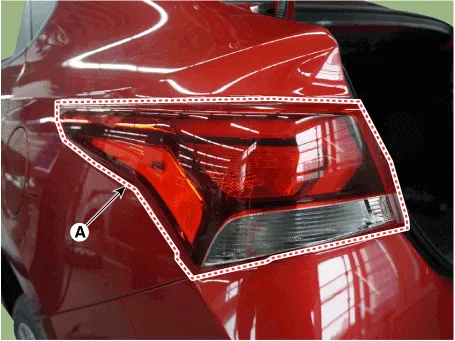
1.Remove the combination lamp cover (A).
2.Disconnect the mounting nuts and rear combination lamp connector (A).
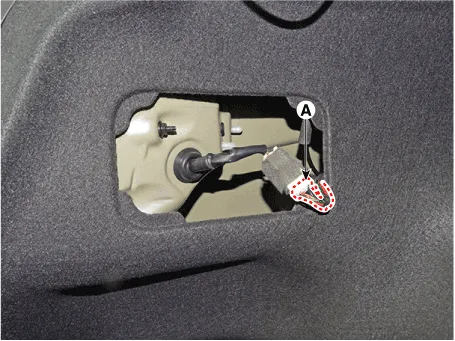
3.Remove the rear combination lamp (A).
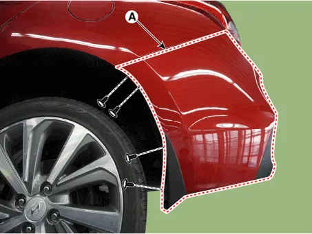
4.After loosening the pin - type retainers and screws on the side of rear bumper (A), detach the side part of rear bumper.

• Be careful not to damage the tabs on the side part of front bumper.
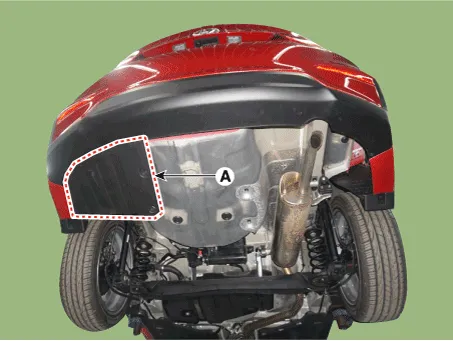
5.Remove the rear bumper side under cover (A) after loosening the mounting nuts and clips.
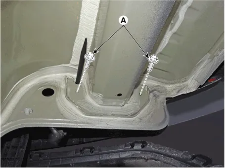
6.Loosen the mounting bolts.
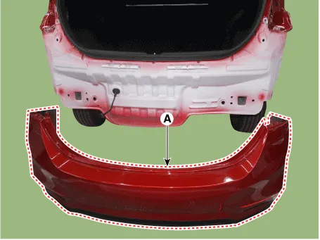
7.Remove the rear bumper assembly (A).
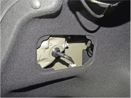
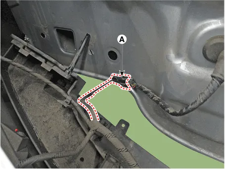
8.Disconnect the rear bumper connector (A).
9.To install, reverse the removal procedure.

• Make sure the connector is plugged in properly.
• Replace any damaged clips (or pin - type retainers).
Rear Bumper beam Assembly
1. Rear bumper beam assembly

• Put on gloves to prevent hand injuries.

• When removing with a flat - tip screwdriver or remover, wrap protective tape around the tools to prevent damage to components.
• When removing the interior trim pieces, use a plastic panel removal tool not to damage the surface.
• Take care not to bend or scratch the trim and panels.
1.Remove the rear bumper assembly.(Refer to Rear Bumper - "Rear Bumper Assembly")
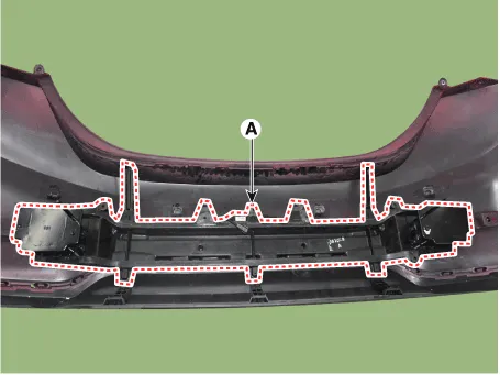
2.Disconnect the rear bumper beam mounting wiring harness (A).
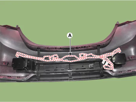
3.After loosening the mounting clips, remove the rear bumper beam assembly (A).
4.To install, reverse the removal procedure.

• Make sure the connector is plugged in properly.
• Replace any damaged clips (or pin - type retainers).


Other information:
Hyundai Accent (HC) (2017 - 2022) Service Manual: CVVT & Camshaft
- Description Continuous Variable Valve Timing (CVVT) system advances or retards the valve timing of the intake and exhaust valve in accordance with the ECM control signal which is calculated by the engine speed and load.By controlling CVVT, the valve over-lap or under-lap occurs, which makes better fuel economy and reduces exhaust gases (NOx, HC) and improves engine performance through reduction of pumping loss, internal EGR effect, improvement of combustion stability, improvement of volumetric efficiency, and increase of expansion work.Hyundai Accent (HC) (2017 - 2022) Service Manual: Warning and Indicator Lights
Information Make sure that all warning lights are OFF after starting the engine. If any light remains ON, it indicates a condition that requires attention. Air Bag Warning Light This warning light illuminates: When the ignition switch is turned to the ON position. - It illuminates for approximately 6 seconds and then turns off. When there is a malfunction in the Supplemental Restraint System (SRS).
Contents
Categories
- Manuals Home
- Hyundai Accent Owners Manual
- Hyundai Accent Service Manual
- Questions & Answers
- Video Guides
- Useful Resources
- New on site
- Most important about car
- Privacy Policy

0.0074