Hyundai Accent (HC): Body Electrical System / Sun Roof
Contents:
Components and Components Location
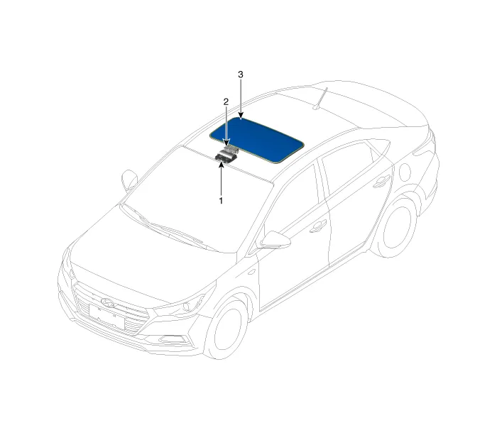
1. Sunroof switch
2. Sunroof motor & controller
3. Sunroof
Schematic Diagrams
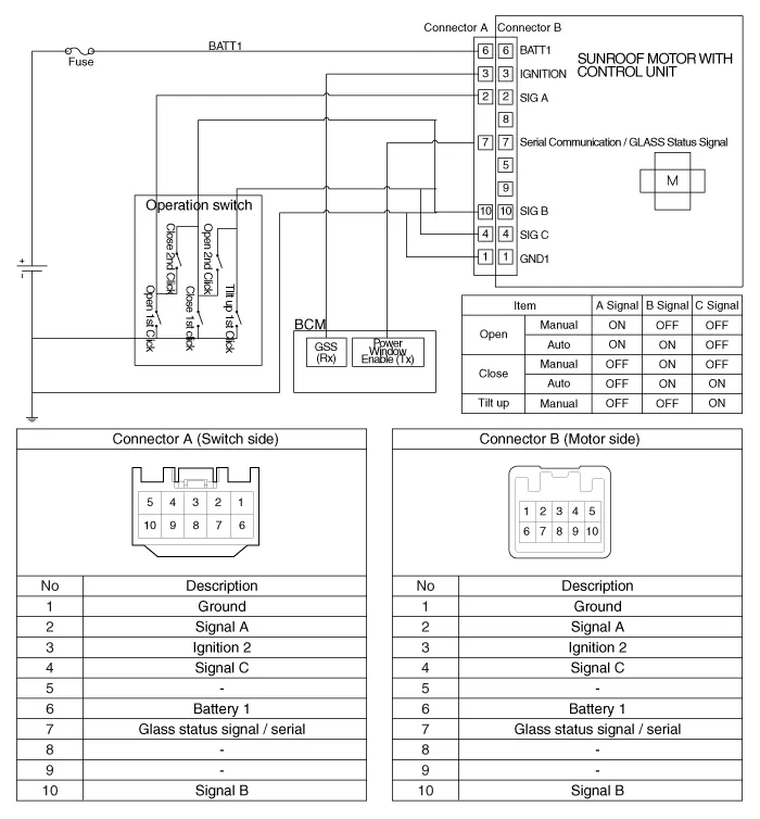
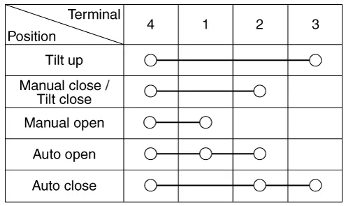
Sunroof Switch
1.Disconnect the negative (-) battery terminal.
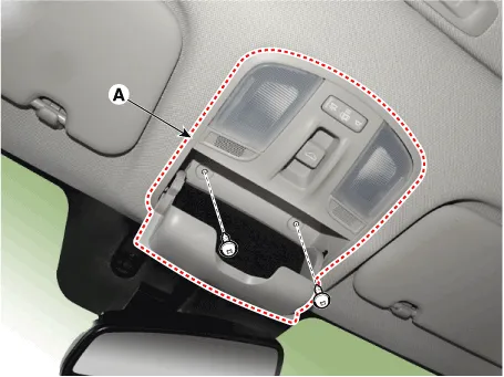
2.Open the sunglass case cover from the overhead console and remove the 2 screws holding the overhead console. Disconnect the switch connector and Map lamp connector, and then remove the overhead console lamp (A).
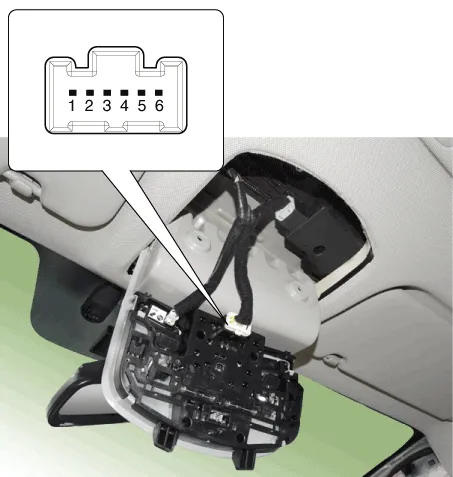
3.Check for continuity between the terminals.
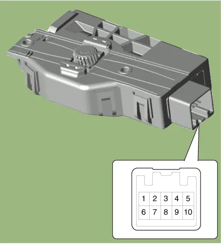
Sunroof Motor
1.Disconnect the negative (-) battery terminal.
2.Remove the roof trim.(Refer to Body - "Roof Trim")
3.Disconnect the sunroof motor connector.
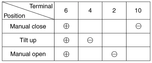
4.Ground the terminals as below table, and check that the sunroof unit operates.

• When inspecting the sunroof motor operation, sunroof motor and roller blind motor always should be connected.
5.Make these input tests at the connector. If any test indicates a problem, find and correct the cause, then recheck the system. If all the input tests prove OK, the sunroof motor must be faulty; replace it.
| Terminal | Test condition | Test : Desired result |
| 3 | IG2 ON | Check for voltage to ground : There should be battery voltage. |
| 1 | Under all conditions | Check for continuity to ground : There should be continuity. |
| 6 | Under all conditions | Check for voltage to ground : There should be battery voltage. |
1.Turn the ignition key to the ON position and then close the sunroof completely.
2.Release the sunroof control lever.
3.Press and hold the CLOSE button for more than 10 seconds until the sunroof closed and it has moved slightly.
4.Release the sunroof control lever.
5.Press and hold the CLOSE button once again within 5 seconds until the sunroof do as follows;
• Tilt → Slide Open → Slide CloseThen release the lever.
6.Reset procedure of panorama system is finished.
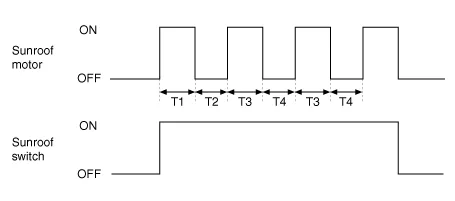
1.The sunroof ECU detects the Run- time of motor
2.Motor can be operated continuously for the 1st run-time (120 ± 10sec.).
3.The continuous operation of motor stops after the 1st Run-time (120 ± 10sec.).
4.Then Motor is not operated for the 1st Cool-time (18 ± 2sec.).
5.Motor is operated for the 2nd Run-time (10 ± 2sec.) at the continued motor operation after 1st Cool-time (18 ± 2sec.)
6.The continuous operation of motor stops operating after the 2nd Run-time (10 ± 2sec.)
7.Motor is not operated for the 2nd Cool-time (18 ± 2sec.).
8.Motor repeats the 2nd run-time and 2nd cool-time at the continued motor operation.
– In case that motor is not operated continuously, the run-time is increased.
– The Run-Time of motor is initialized to "0" if the battery or fuse is reconnected after being disconnected, discharged or blown.


Other information:
The Smartstream Intelligent Variable Transmission (Smartstream IVT) in the Hyundai Accent automatically adjusts its driving ratios based on vehicle speed and accelerator pedal position. The appropriate “speed” (ratio) is selected automatically according to the shift lever position and current driving conditions, helping deliver smooth acceleration and efficient performance.Hyundai Accent (HC) (2017 - 2022) Service Manual: Repair procedures
- Removal 1.Remove the air cleaner assembly.(Refer to Engine Mechanical System - "Air cleaner") 2.Remove the battery and battery tray.(Refer to Body Electrical System - "Battery") 3.Drain the coolant.(Refer to Engine Mechanical System - "Coolant") 4.Disconnect the position switch connector (A). 5.Disconnect the driven pully speed sensor connector (B).
Contents
Categories
- Manuals Home
- Hyundai Accent Owners Manual
- Hyundai Accent Service Manual
- Questions & Answers
- Video Guides
- Useful Resources
- New on site
- Most important about car
- Privacy Policy

0.0042