Hyundai Accent: Lighting System / Head Lamps
[General]
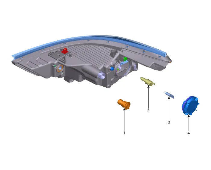
1. Turnsignal lmap bulb
2. High / Low Beam bulb
3. Position lamp
4. Dust cap
[Bi-Function]
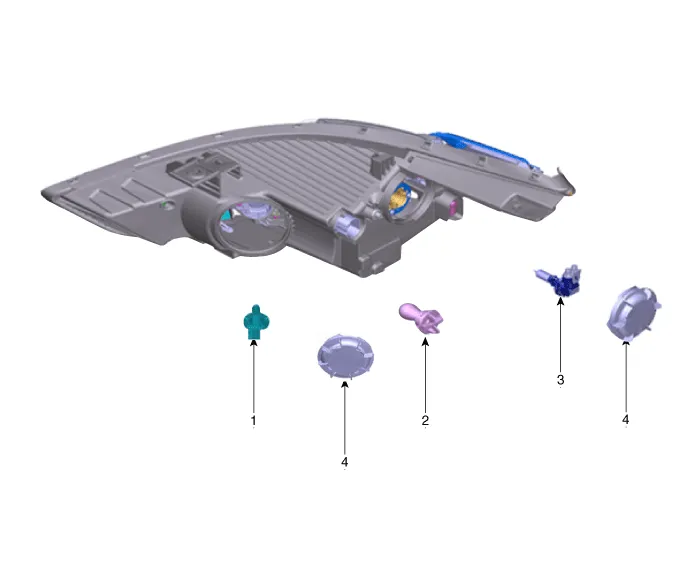
1. Static bending light bulb
2. Turnsignal lamp bulb
3. High / Low Beam bulb
4. Dust cap
1.BI-FUNCTION
(1)Definition
– A headlamp with integrated functions of high and low beam.
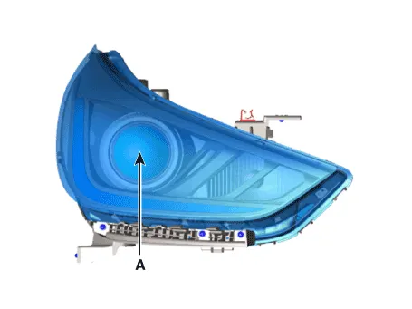
– The light is controlled by rotating the shield inserted to the lens (A solenoid is adopted)
(2)Structure and mechanism
– Case of working as a low beam:The light illuminates to the restricted area of low beam by blocking the light with the stopped shield.
– Case of working as a high beam:The light is not blocked by the open shield and the light illuminates to the area of high beam.
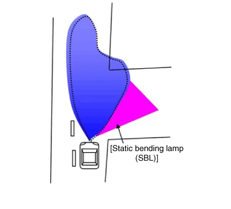
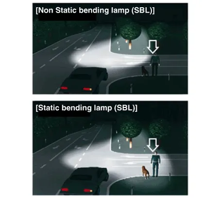
2.Static Bending Light (SBL)
(1)Definition
– Acquires visibility in corner when turning at night.
– L/R Static Bending Lamp is turned ON/OFF based on the vehicle speed and steering wheel angle.
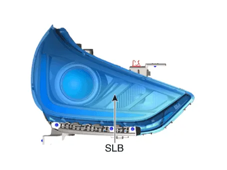
(2)Vehicle Input Factors : Vehicle speed, steering wheel angle


1.Disconnect the negative (-) battery terminal.
2.Remove the front bumper cover.(Refer to Body - "Front Bumper Cover")
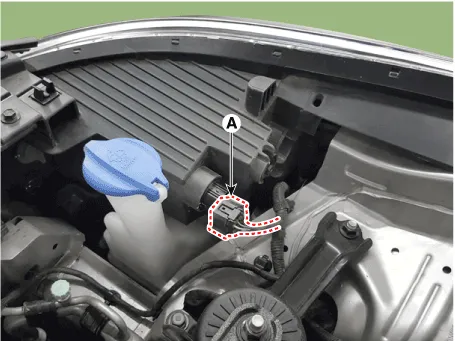
3.Disconnect the lamp connector (A) from the head lamp assembly.
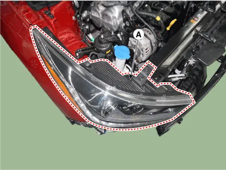
4.Remove the head lamp assembly (A) after loosening the mounting bolts.

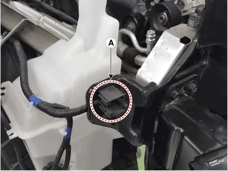
1.Install the head lamp bulbs.
2.Reassemble the head lamp bulb covers.
3.Reassemble the head lamp assembly after connecting the lamp connector.
General Head Lamp Bulb
1.Turn the head lamp switch off.
2.Disconnect the power connector from the lamp.
3.Remove the dust cap (A).
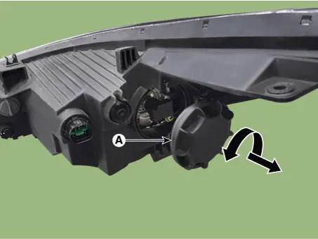
4.Disconnect the connector (A) from the bulb.
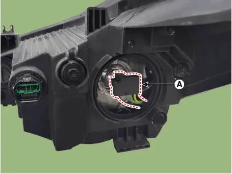
5.Disengaging the retaining clip (A).
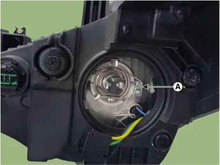
6.Remove the heam lamp High/Low beam bulb (A).
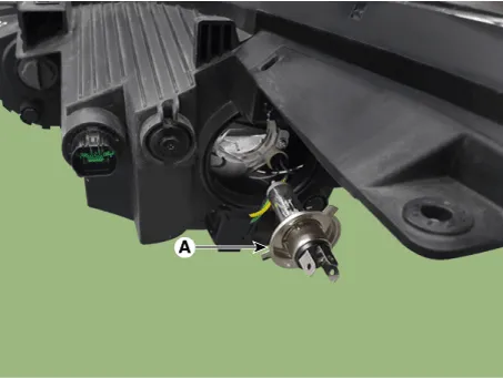
7.Installation is the reverse of removal.
Bi-Function Head Lamp Bulb
1.Turn the head lamp switch off.
2.Disconnect the power connector from the lamp.
3.Remove the dust cap (A) after turning the dust cap counterclockwise.
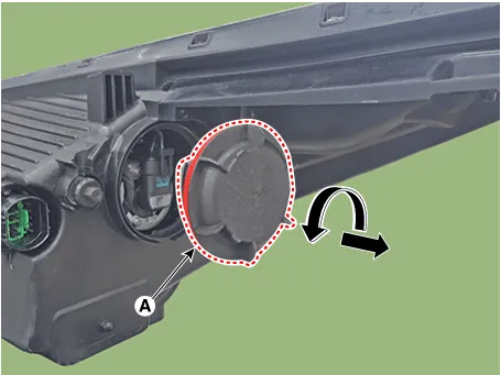
4.Replace the head lamp bulb (A) after turning the bulb socket counterclockwise and disconnecting the connector(B).
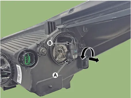
5.Installation is the reverse of removal.
Static bending light (SBL)
1.Turn the head lamp switch off.
2.Disconnect the power connector from the lamp.
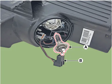
3.Remove the dust cap (A) after turning the dust cap counterclockwise.
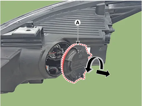
4.Remove the static bending lignt bulb (A) after disconnecting the connector (B).
5.Installation is the reverse of removal.
Turn Signal Lamp
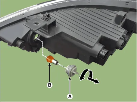
1.Turn the head lamp switch off.
2.Remove the bulb socket (A) and bulb (B) from the lamp assembly.

1.Inflate the tires to the specified pressure and remove any loads from the vehicle except the driver, spare tire, and tools.
2.The vehicle should be placed on a flat floor.
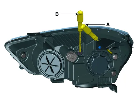
3.Draw vertical lines (Vertical lines passing through respective head lamp centers) and a horizontal line (Horizontal line passing through center of head lamps) on the screen.
4.With the head lamp and battery in normal condition, aim the head lamps so the brightest portion falls on the horizontal and vertical lines.A : HorizontalB : Vertical
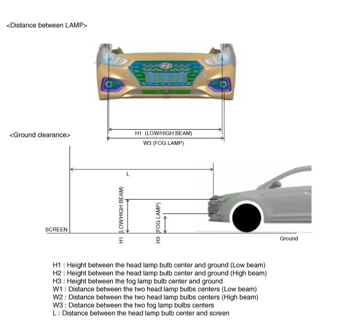
| Specifications | Vehicle condition | H1 | H3 | W1 | W3 | L |
| Standard | Without driver | 27.4 (697) | 16.2 (412) | 54.9 (1394) | 55.3 (1405) | Refer to aiming condition |
| With driver | 27.1 (689) | 15.9 (404) | 54.9 (1394) | |||
| Option | Without driver | 27.5 (705) | - | 55.0 (1397) | - | |
| With driver | 27.4 (697) | 55.0 (1397) |
| Specifications | Vehicle condition | H1 | H3 | W1 | W3 | L |
| Standard | Without driver | 28.0 (712) | 16.8 (427) | 54.9 (1394) | 55.3 (1405) | Refer to aiming condition |
| With driver | 27.7 (704) | 16.4 (419) | 54.9 (1394) | |||
| Option | Without driver | 28.3 (720) | - | 55.0 (1397) | - | |
| With driver | 28.0 (712) | 55.0 (1397) |
| Specifications | Vehicle condition | H1 | H3 | W1 | W3 | L |
| Standard | Without driver | 27.0 (687) | 15.8 (402) | 54.9 (1394) | 55.3 (1405) | Refer to aiming condition |
| With driver | 26.7 (679) | 15.5 (394) | 54.9 (1394) | |||
| Option | Without driver | 27.3 (695) | - | 55.0 (1397) | - | |
| With driver | 27.0 (687) | 55.0 (1397) |
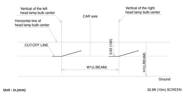
1.Head Lamp (Low beam)
– Turn the low beam on without driver aboard.
– The cut-off line should be projected in the cut-off line shown in the picture.
– When aiming the low beam, vertical aiming shuld be adjusted after adjusting the horizontal aiming.
– If head lamp leveling device is equipped, adjust the head lamp leveling device switch with 0 positions.
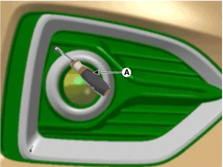
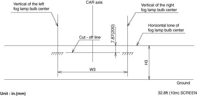
2.Turn the front fog lamp on without the driver aboard.The cut-off line should be projected in the allowable range (shaded region)
Other information:
Hyundai Accent (HC) (2017 - 2022) Service Manual: Blower Unit
- Component Location 1. Blower unit assembly - Components 1. Seal2. Intake duct case3. Intake actuator4. Intake door5. Intake lower case6. Blower upper case7. Blower unit pad8. Blower lower case9. Blower motor10. Air filter11. Air filter cover12. PWM Blower module - Replacement When prying with a flat-tip screwdriver or use a prying trim tool, wrap it with protective tape, and apply protective tape around the related parts, to prevent damage.Hyundai Accent (HC) (2017 - 2022) Service Manual: Ignition Lock Switch
- Specifications ItemSpecifications Working voltageDC 12.5V ± 0.3V Operating forceInitial position : 0.25 ± 0.15N(0.025 ± 0.015kg, 0.056 ± 0.034lb) Full position : 0.8 ± 0.2 N(0.08 ± 0.02 kgf, 0.579 ± 0.014 lb-ft) Working temperature-40℃ ~ 80℃ (-40℉ ~ 176℉) - Description – Ignition lock switch is mounted on the clutch pedal.
Categories
- Manuals Home
- Hyundai Accent Owners Manual
- Hyundai Accent Service Manual
- New on site
- Most important about car


