Hyundai Accent: Engine Electrical System / Charging System
Description and Operation
Repair procedures ➤
Troubleshooting ➤
Alternator ➤
Battery ➤
Battery Sensor

• When battery sensor signal fault occurs, check whether the parasitic draw is not abnormal (Refer to vehicle parasitic current inspection)

1)Turn the ignition switch ON/OFF.
2)Leave the vehicle in parking mode for more than 4 hours.
3)After 4 hours, check that the SOC (State of charge) of battery is displayed on GDS properly.

• When replacing the battery, it should be the same (type, capacity and brand) as originally installed on your vehicle. If a battery of a different type is installed, the battery sensor may recognize the battery to be abnormal.
• When installing the ground cable on the negative post of battery, tighten the clamp with specified torque of 3.9 - 5.9 N.m (0.4 - 0.6 kgf.m, 3.0 - 4.4 lb-ft). An excessive tightening torque can damage the PCB internal circuit and the battery terminal.
• When recharging the battery, ground the negative terminal of the booster battery to the vehicle body.
1.Turn the ignition switch OFF.
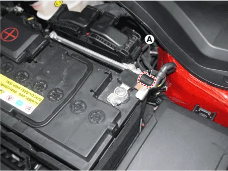
2.Disconnect the battery negative (-) terminal (A).
Battery negative (-) terminal tightening nut :8.0 - 10.0 N.m (0.8 - 10.0 kgf.m, 5.9 - 7.4 lb-ft)
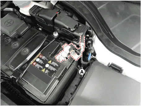
3.Disconnect the battery sensor connector (A).
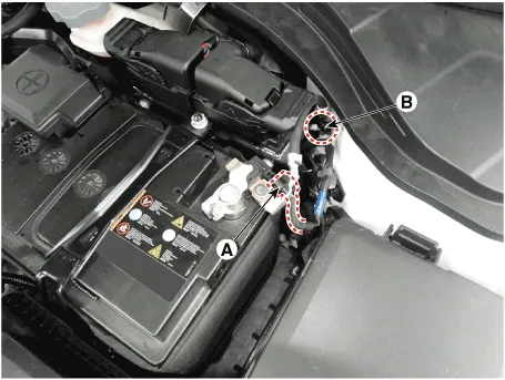
4.Remove the battery sensor by loosening the mounting bolts (B).
Battery sensor cable mounting bolt (Chassis ground) :27.0 - 33.0 N.m (2.8 - 3.4 kgf.m, 19.9 - 24.3 lb-ft)
5.Install in the reverse order of removal.

• For the vehicle equipped with a battery sensor, be careful not to damage the battery sensor when the battery is replaced or recharged.
1)When replacing the battery, it should be same one (type, capacity and brand) that is originally installed on your vehicle. If a battery of a different type is replaced, the battery sensor may recognize the battery to be abnormal.
2)When installing the ground cable on the negative post of battery, tighten the clamp with specified torque. An excessive tightening torque can damage the PCB internal circuit and the battery terminal.
3)When recharging the battery, ground the negative terminal of the booster battery to the vehicle body.
1.Turn the Iginition switch ON and OFF.
2.Park the vehicle for about 4 hours with the hood and all doors closed.


Other information:
Hyundai Accent (HC) (2017 - 2022) Service Manual: Electric EGR Control Valve
- Description The Electric EGR Control Valve is installed in between the EGR cooler and the exhaust line and is a solenoid valve. This valve controls EGR (Exhaust Gas Recirculation) amount by the ECM's duty control signal depending on engine load and the need of intake air.The Exhaust Gas Recirculation (EGR) system is used to add the exhaust gas to intake air in order to reduce an excess of air and the temperature in the combustion chamber.Hyundai Accent (HC) (2017 - 2022) Service Manual: Repair procedures
- A/S Repair produres MDPS System A/S Workflow ① Noise / malfunction Inspection ② Warning lamp (DTC) / CAN Line error 2 - 1 Checking Connectors and Wiring 1.Checking Connectors and Wiring.Check for damage, push-back, or improper connection in each connector and wiring.(1)Check the wiring on the vehicle side. – Check for open / short - circuit due to faulty connection, damage, or foreign substance.
Contents
Categories
- Manuals Home
- Hyundai Accent Owners Manual
- Hyundai Accent Service Manual
- New on site
- Most important about car