Hyundai Accent: Cooling System / Cooling Fan
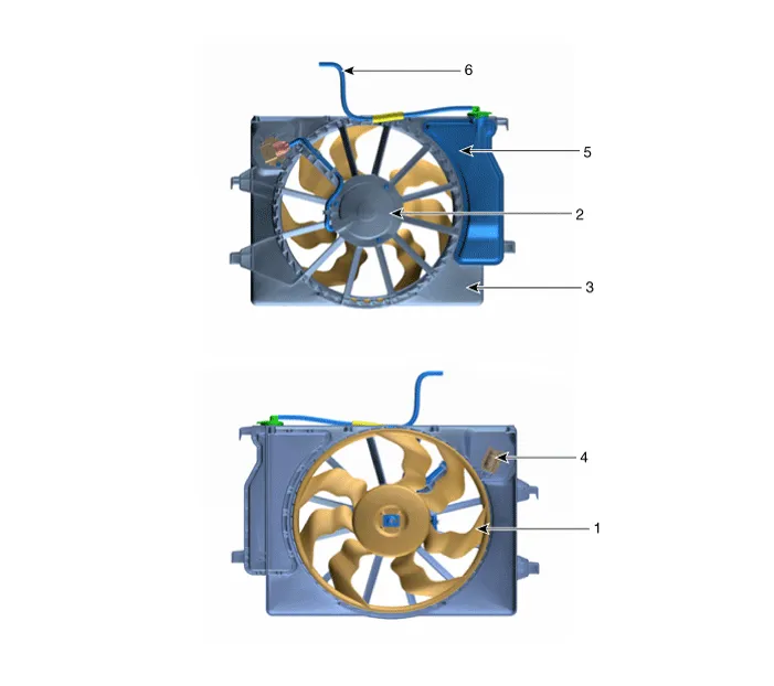
1. Cooling fan
2. Fan motor
3. Cooling fan shroud
4. Resister
5. Reservoir tank
6. Over flow hose
1.Disconnect the battery negative terminal.
2.Remove the air duct.(Refer to Intake and Exhaust System - "Air Cleaner")
3.Remove the engine room under cover.(Refer to Engine and Transaxle Assembly - "Engine Room Under Cover")
4.Drain the coolant.(Refer to Cooling System - "Coolant")
5.Remove the front bumper.(Refer to Body (Interior and Exterior) - "Front Bumper")
6.Remove the horn.(Refer to Body Electrical System - "Horn")
7.Disconnect the wiring harness connector (A).
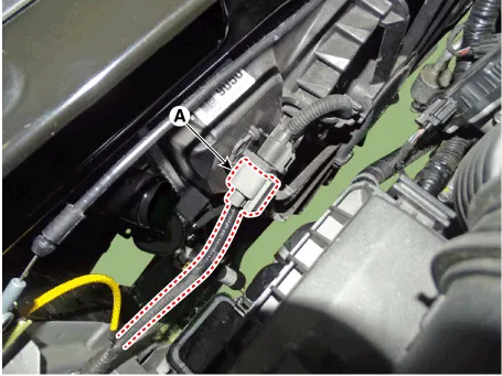
8.Disconnect the over flow hose (A).
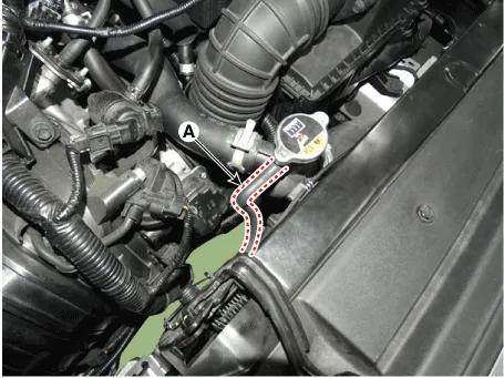
9.Remove the intake shield (A).
Tightening torque: 7.8 - 9.8 N.m (0.8 - 1.0 kgf.m , 5.8 - 7.2 lb-ft)
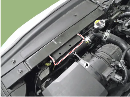
10.Disconnect the radiator upper hose (A).
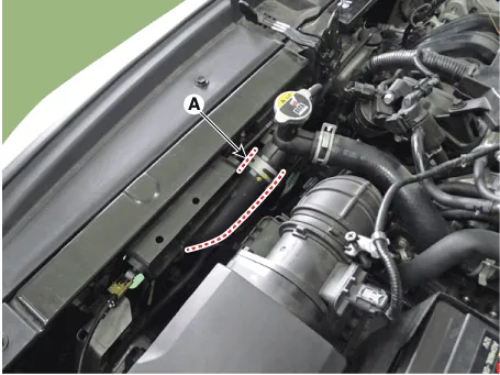
11.Remove the side air guard (A).
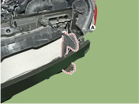
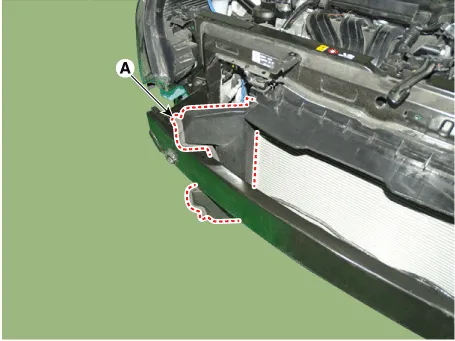
12.Remove the air intake shield (A).
Tightening torque: 7.8 - 11.8 N.m (0.8 - 1.2 kgf.m, 5.8 - 8.7 lb-ft)
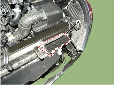
13.Remove the radiator mounting bracket bolts (A).
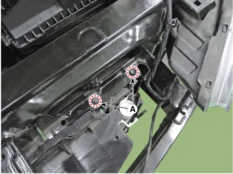
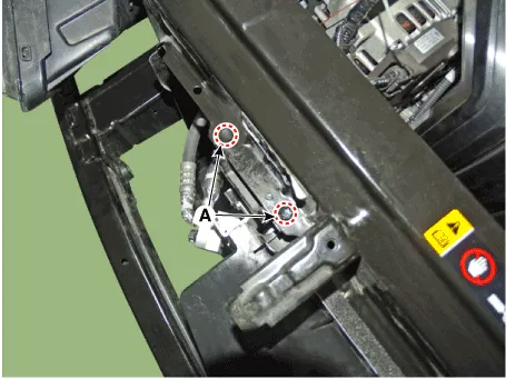
14.remove the ambient temperature sensor bracket mounting bolt (A).
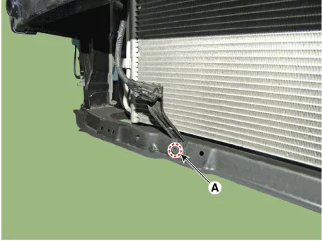
15.Remove the upper air guard.
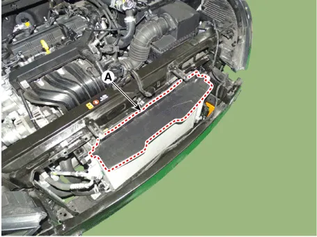
16.Separate the A/C condenser from the radiator assembly.
17.Remove the cooling fan assembly (A).
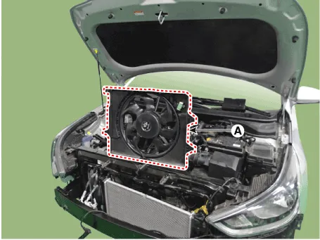
18.Install in the reverse order of removal.
19.Fill with engine coolant. (Refer to Cooling System - "Coolant")

• The coolant must be injected according to the integrated thermal management module (ITM) coolant filling method.
1.Disconnect the battery negative terminal.
2.Remove the air duct.(Refer to Intake and Exhaust System - "Air Cleaner")
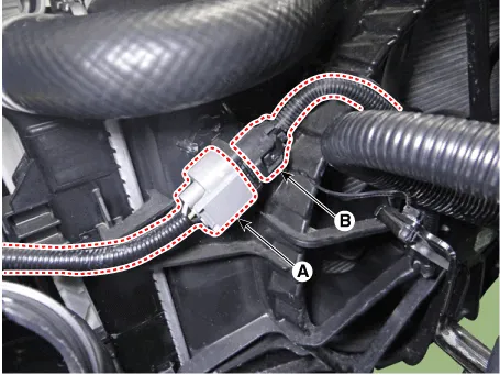
3.Disconnect the wiring harness connector (A) and cooling fan motor connector (B).
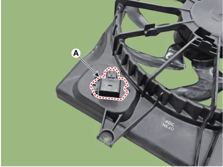
4.Remove the resistor (A).
Tightening torque :1.8 - 2.5 N.m (0.18 - 0.25 kgf.m, 1.3 - 1.8 lb-ft)
5.Install in the reverse order of removal.
1.Disconnect the cooling fan motor connector (A).
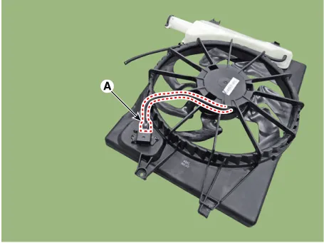
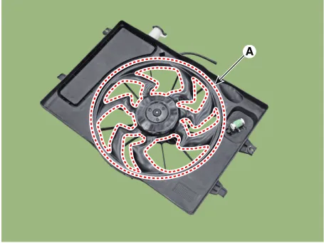
2.Remove the cooling fan (A) from the cooling fan assembly.
Tightening torque :2.8 - 3.2 N.m (0.28 - 0.33 kgf.m, 2.0 - 2.4 lb-ft)
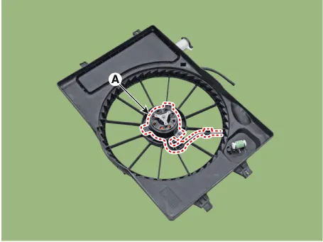
3.Remove the fan motor (A) from the cooling fan shroud.
Tightening torque :3.9 - 5.9 N.m (0.4 - 0.6 kgf.m, 2.9 - 4.3 lb-ft)
4.Install in the reverse order of removal.
1.Turn ignition switch "OFF" and connect the GDS to the Data Link Connector.
2.With the gear shift in P (Park) position and ignistion switch "ON" (LED of the Power button illuminates in Red), select the "force drive" function.
3.Force drive the cooling fan motor.
(1)Start the "Fan motor low speed" of the force drive function.

(2)Press the start button and force drive for 5 seconds.
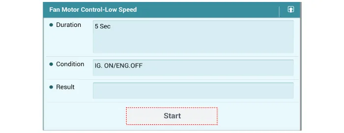
(3)Visually check the operation of the cooling fan.
Other information:
Hyundai Accent (HC) (2017 - 2022) Service Manual: Troubleshooting
- Troubleshooting SymptomPossible causeRemedy Hard steeringImproper front wheel alignmentExcessive turning resistance of lower arm ball jointLow tire pressureNo power assistCorrectReplaceAdjustRepair and replace Poor return of steering wheel to centerImproper front wheel alignmentCorrect Poor or rough rideImproper front wheel alignmentMalfunctioning shock absorberBroken or worn stabilizerBroken or worn coil springWorn lower arm bushingCorrectRepair or replaceReplaceReplaceReplace the lowerHyundai Accent (HC) (2017 - 2022) Service Manual: Specifications
- Specifications Ignition System Ignition Coil ItemSpecification Rated Voltage (V)13.5 Operation Voltage (V)6 - 16 ItemSpecification Engine Speed (RPM)100020003000400050006000 Dwell Time (ms)3.43.43.42.92.72.5 Secondary Coil Voltage (kV)40 ↑40 ↑40 ↑40 ↑40 ↑38 ↑ Spark plug ItemSpecification TypeSILZKR7E9 Gap0.8 - 0.9 mm (0.
Categories
- Manuals Home
- Hyundai Accent Owners Manual
- Hyundai Accent Service Manual
- New on site
- Most important about car


