Hyundai Accent: Engine Mechanical System / Cylinder Block
Components and Components Location
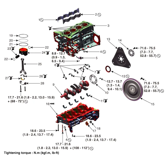
1. RH Water jacket insert
2. LH Water jacket insert
3. Cylinder block
4. O-ring
5. Piston cooling oil jet
6. Crankshaft upper bearing (No.1, 3, 5 journal)
7. Thrust bearing
8. Crankshaft upper bearing (No.2, 4 journal)
9. Crankshaft
10. Crankshaft position sensor wheel
11. Crankshaft lower bearing
12. Rear oil seal
13. Drive plate
14. Drive plate adapter
15. Flywheel
16. Lower crankcase
17. Exus hole cover
18. Rear cap
19. Piston ring (Top ring)
20. Piston ring (Second ring)
21. Piston ring (Oil ring)
22. Snap ring
23. Piston pin
24. Piston
25. Connecting rod
26. Connecting rod upper bearing
27. Connecting rod lower bearing
28. Connecting rod bearing cap
Water Jacket Insert
1.Remove the cylinder head. (Refer to Cylinder Head Assembly - "Cylinder Head")
2.Remove the RH water jacket insert (A) and LH water jacket insert (B).
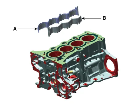

• When removing the water jacket insert, Be careful not to damage the top surfaces of the cylinder block.
3.Install in the reverse order of removal.

• Always use a new water jacket insert.
• Install the upper surface of the water jacket insert below the upper surface of the cylinder block.
• When installing water jacket insert, check LH, RH classification and installing direction.
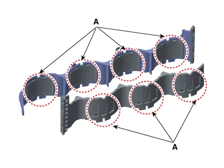
• When installing a new water jacket insert, check the lip seal (A) and the cylinder block mounting surface for foreign matters.
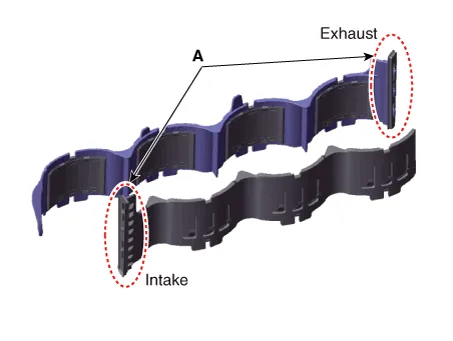
• When installing a new water jacket insert, do not press the sus spring (A).
Drive Plate
1.Remove the intelligent variable transmission (IVT).Remove the automatic transaxle.(Refer to Intelligent Variable Transmission (IVT) System - "Intelligent Variable Transmission (IVT)")
2.Remove the drive plate adapter (A) and drive plate plate (B).
Tightening torque :71.5 - 75.5 N.m (7.3 - 7.7 kgf.m, 52.8 - 55.6 lb-ft)
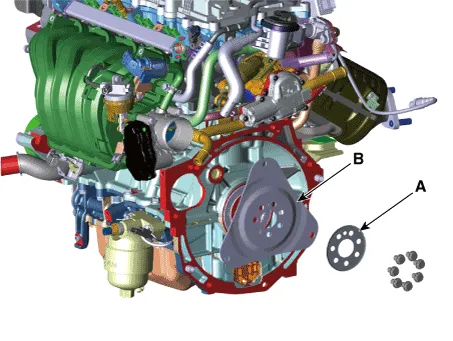

• Always use a new drive plate mounting bolts.
3.Install in the reverse order of removal.
Flywheel
1.Remove the manual transaxle.(Refer to Manual Transaxle System - "Manual Transaxle")
2.Remove the clutch cover.(Refer to Clutch System - "Clutch Cover And Disc")
3.Remove the flywheel (A).
Tightening torque :71.6 - 75.5 N.m (7.3 - 7.7 kgf.m, 52.8 - 55.6 lb-ft)
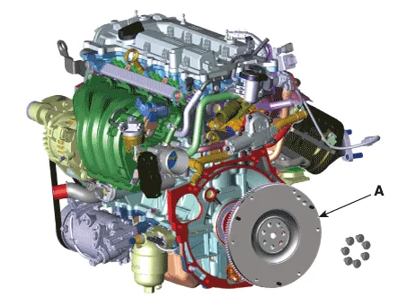

• Always use a new flywheel mounting bolts.
4.Install in the reverse order of removal.
Rear Oil Seal
1.Remove the transaxle assembly from the engine assembly.Intelligent variable transmission (IVT)(Refer to Intelligent Variable Transmission (IVT) System - "Intelligent Variable Transmission (IVT)")Manual transaxle(Refer to Manual Transaxle System - "Manual Transaxle")
2.Intelligent variable transmission (IVT) : Remove the drive plate.(Refer to Cylinder Block - "Drive Plate")Manual transaxle : Remove the flywheel.(Refer to Cylinder Block - "FlyWheel")
3.Remove the rear oil seal (A).
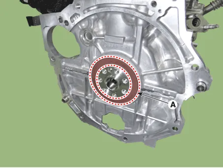
4.Apply engine oil on the edge of new rear oil seal.
5.Using SSTs (09231-H1100, 09231-2B200), install the new rear oil seal. The oil seal installation depth is 0.5 mm (0.0197 in) from the cylinder block face.
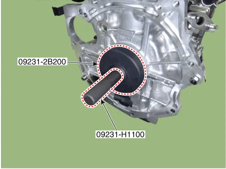

• Always use a new rear oil seal.
6.Install the other parts in the reverse order of removal.
Piston and Connecting Rod ➤
Crankshaft ➤
Cylinder Block ➤
Other information:
Hyundai Accent (HC) (2017 - 2022) Service Manual: Description and Operation
- Description MDPS (Motor Driven Power Steering) system uses an electric motor to assist the steering force and it is an engine operation independent steering system.MDPS control module controls the motor operation according to information received from the each sensor and CAN (Controller Area Network), resulting in a more precise and timely control of steering assist than conventional engine-driven hydraulic systems.Hyundai Accent (HC) (2017 - 2022) Service Manual: Position Switch
- Specifications ItemSpecification Power supply (V)4.5 - 5.5V Output typePWM (S1, S2), ON/OFF (Ps, Ns) - Component Location 1. Position switch2. Manual control lever - Circuit Diagram - Inspection • Inspect the connector thoroughly for looseness, poor connection, bending, corrosion, contamination, deformation, or damage.
Contents
- Components and Components Location
- Water Jacket Insert
- Drive Plate
- Flywheel
- Rear Oil Seal
- Piston and Connecting Rod
- Crankshaft
- Cylinder Block
Categories
- Manuals Home
- Hyundai Accent Owners Manual
- Hyundai Accent Service Manual
- New on site
- Most important about car


