Hyundai Accent: ABS(Anti-Lock Brake System) / Description and Operation
– Input of signal from the wheel speed sensors attached to each wheel.
– Control of braking force.
– Failsafe function.
– Self diagnosis function.
– Interface with the external diagnosis tester.
– Brake tube length from Master cylinder port to HECU inlet port should be max. 1m
– The position should not be close to the engine block and not lower than the wheel.
– OvervoltageWhen overvoltage is detected(above 16.8 V), the ECU switches off the valve relay and shuts down the system.When voltage is returned to operating range, the system goes back to the normal condition after the initialization phase.
– UndervoltageIn the event of undervoltage(below 9.3 V), ABS control shall be inhibited and the warning lamp shall be turned on.When voltage is returned to operating range, the warning lamp is switched off and ECU returns to normal operating mode.
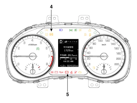
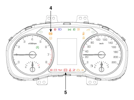
1.ABS Warning LampThe active ABS warning lamp indicates the selftest and failure status of the ABS. The ABS warning lamp shall be on :
– During the initialization phase after IGN ON. (continuously 3 seconds).
– In the event of inhibition of ABS functions by failure.
– During diagnostic mode.
– When the ECU Connector is separated from ECU.
2.EBD/Parking brake Warning LampThe active EBD warning lamp indicates the selftest and failure status of the EBD. However, in case the Parking Brake Switch is turned on, the EBD warning lamp is always turned on regardless of EBD functions.The EBD warning lamp shall be on:
– During the initialization phase after IGN ON. (continuously 3 seconds).
– When the Parking Brake Switch is ON or brake fluid level is low.
– When the EBD function is out of order.
– During diagnostic mode.
– When the ECU Connector is separated from ECU.
1.Normal Braking without ABS
| Inlet valve (IV) | Outlet valve (OV) | Return pump | |
| Operation | Open | Close | OFF |
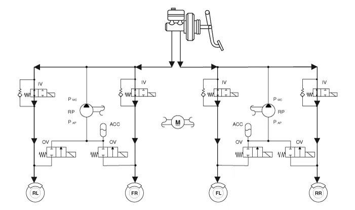

• IV : Inlet Valve
• OV : Outlet Valve
• RL : Rear left wheel
• FR : Front right wheel
• FL : Front left wheel
• RR : Rear right wheel
• RP : Return pump
2.Decrease Mode
| Inlet valve (IV) | Outlet valve (OV) | Return pump | |
| Operation | Close | Open | ON (Motor speed control) |
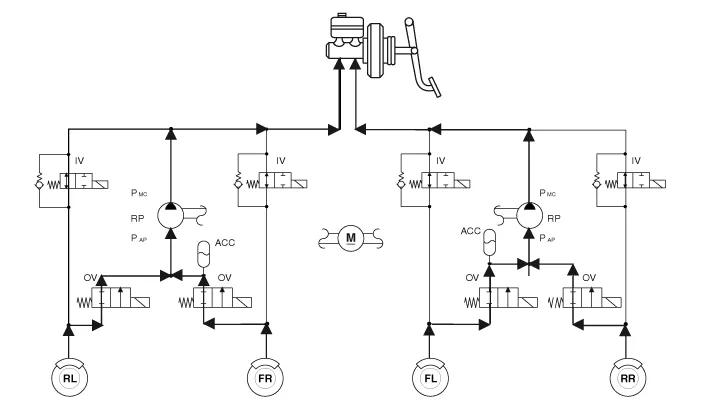

• IV : Inlet Valve
• OV : Outlet Valve
• RL : Rear left wheel
• FR : Front right wheel
• FL : Front left wheel
• RR : Rear right wheel
• RP : Return pump
3.Hold Mode
| Inlet valve (IV) | Outlet valve (OV) | Return pump | |
| Operation | Close | Close | ON (Motor speed control) |
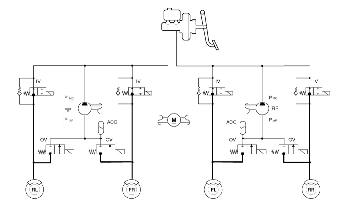

• IV : Inlet Valve
• OV : Outlet Valve
• RL : Rear left wheel
• FR : Front right wheel
• FL : Front left wheel
• RR : Rear right wheel
• RP : Return pump
4.Increase Mode
| Inlet valve (IV) | Outlet valve (OV) | Return pump | |
| Operation | Open | Close | ON (Motor speed control) |
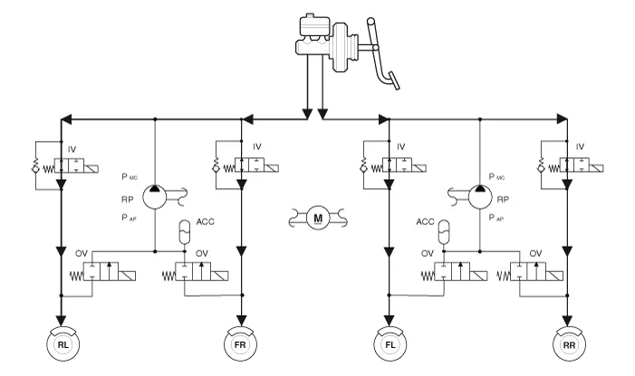

• IV : Inlet Valve
• OV : Outlet Valve
• RL : Rear left wheel
• FR : Front right wheel
• FL : Front left wheel
• RR : Rear right wheel
• RP : Return pump
Other information:
Hyundai Accent (HC) (2017 - 2022) Service Manual: Brake Oil
- Specifications Brake oil : DOT 3 or DOT 4 Reservoir capacity (cc) MAX LEVELA + B + C + D + E409 ± 20 ON LEVEL (MIN LEVEL)(H = 23 ± 1.5 mm)B + C + D138 ± 10 PARTIAL LEVELC (PRI)28 D (SEC)31 CLUTCH LEVELE12 - Replacement 1.Disconnect the battery (-) terminal. 2.Remove the brake fluid level sensor connector. 3.Remove the reservoir cap and remove the brake fluid from the reservoir tank using the cleaner.Hyundai Accent (HC) (2017 - 2022) Service Manual: Stop Lamp Switch
- Components 1. Brake pedal member assembly2. Stop lamp switch3. Brake pedal arm 4. Pedal pad - Schematic Diagram - System circuit diagram - Terminal function TerminalDescription 1IGN 2BS 3- 4B+ 5BLS 6GND - Adjustment 1.Turn ignition switch OFF and disconnect the negative (-) battery cable. 2.Remove the lower crash pad.
Categories
- Manuals Home
- Hyundai Accent Owners Manual
- Hyundai Accent Service Manual
- New on site
- Most important about car


