Hyundai Accent: IVT Control System / Driven Pulley Pressure Sensor
| Item | Specification |
| Pressure (Mpa) | 0 - 6 |
| Temp [(˚C)˚F] | (-40 to 140) -40 to 284 |
| Output voltage (V) | 5 |
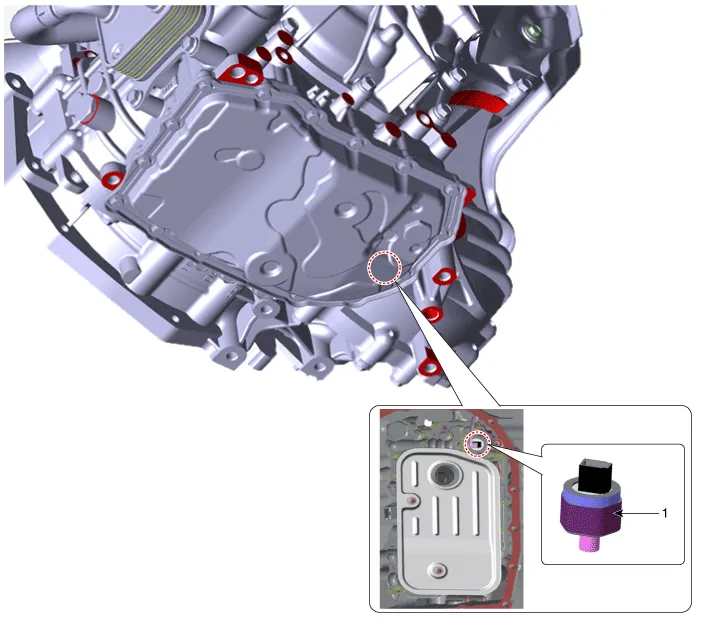
1. Driven pulley pressure sensor

• Maintain clean condition so that foreign substance does not get into the Intelligent Variable Transmission (IVT).
• Use a coated apron, latex gloves, and stainless tray to prevent foreign substance.
• Intelligent Variable Transmission (IVT) is composed of delicate components. Be careful not to cause any damage on the component when assembling and disassembling.
1.Disconnect the negative (-) battery cable.
2.Remove the engine room under cover.(Refer to Engine Mechanical System - "Engine Room Under Cover")
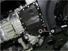
3.Remove the IVTF drain plug (A), allow the fluid to drain out and then reinstall the drain plug.
Tightening torque :34.3 - 39.2 N.m (3.5 - 4.0 kgf.m, 25.3 - 28.9 lb-ft)

• Do not reuse Intelligent Variable Transmission Fluid(IVTF).
• The existing IVTF drain plug gasket must be replaced with a new one (do not reuse).
4.Remove the valve body cover (A) after removing the bolts.


• Be careful when removing the valve body cover because the remaining IVTF remains in the valve body cover.
5.Remove the IVTF filter (A) after removing the bolts.
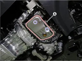
6.Disconnect the driven pulley pressure sensor connector (A).
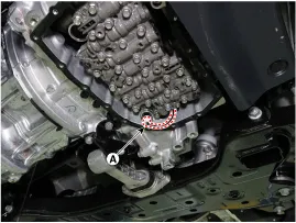
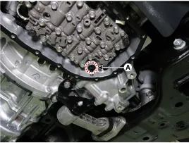
7.Remove the driven pulley pressure sensor (A).

• Maintain clean condition so that foreign substance does not get into the Intelligent Variable Transmission (IVT).
• Use a coated apron, latex gloves, and stainless tray to prevent foreign substance.
• Intelligent Variable Transmission (IVT) is composed of delicate components. Be careful not to cause any damage on the component when assembling and disassembling.
1.Install the driven pulley pressure sensor (A).
Tightening torque :11.8 - 13.7 N.m (1.2 - 1.4 kgf.m, 8.7 - 10.1 lb-ft)
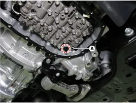
2.Connect the driven pulley pressure sensor connector (A).
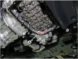
3.Install the IVTF filter (A).
Tightening torque :9.8 - 11.8 N.m (1.0 - 1.2 kgf.m, 7.2 - 8.7 lb-ft)
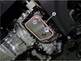
4.Install the oil pan (A).
Tightening torque :9.8 - 11.8 N.m (1.0 - 1.2 kgf.m, 7.2 - 8.7 lb-ft)
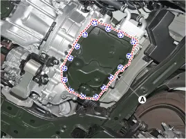

• The existing valve body cover gasket must be replaced with a new one (do not reuse).
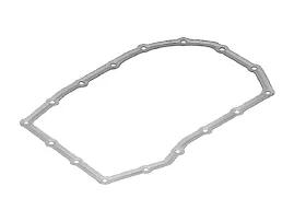
• Visually check the reference hole (A) to align the valve body cover hole with the gasket hole.
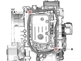
| Hole match: Assembly possible | Hole inconsistency: Oil leakage when assembled |
|
|
5.Check the IVTF level after refilling the intelligent variable transmission with fluid.(Refer to Hydraulic System - "Fluid")
6.Check for leakage of IVT fluid from engine start.
7.Install the engine room under cover.(Refer to Engine Mechanical System - "Engine Room Under Cover")
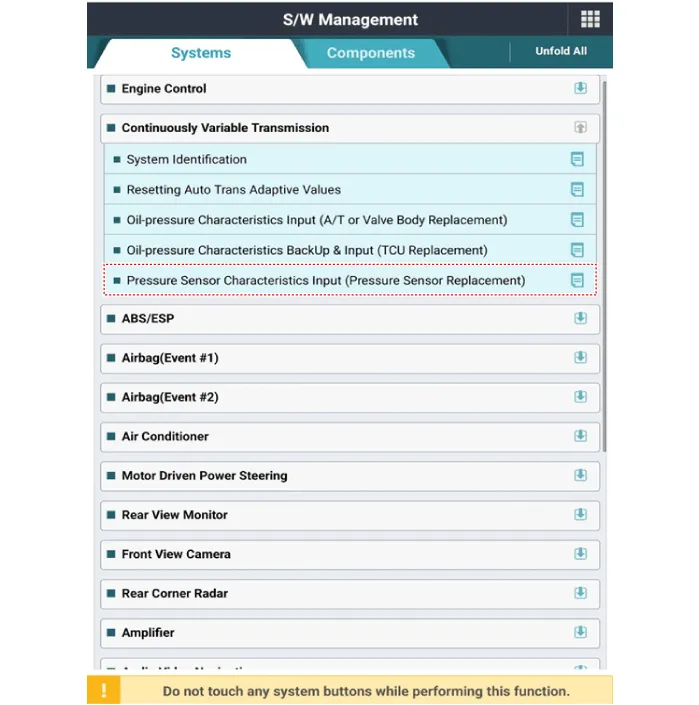
8.Perform the pressure sensor characteristics input using the diagnostic tool. (When replacing the pressure sensor)

• Input '76' in the characteristic value input field.
9.In order to avoid any problem including sense of starting delay of the transmission and shock at acceleration and vehicle start, make sure to process learning.(Refer to IVT Control System - "Adjustment")
Other information:
Hyundai Accent (HC) (2017 - 2022) Service Manual: TJ Joint
- Components [RH] 1. BJ assembly 2. BJ circlip 3. BJ boot band 4. BJ boot 5. Dynamic damper band 6. Dynamic damper7. Shaft8. TJ boot band9. TJ boot10. Spider assembly11. Snap ring12. TJ case13. Clip [LH] 1. BJ assembly 2. Circlip 3. BJ boot band 4. BJ boot 5. Shaft6. TJ boot band7. TJ boot8. Spider assembly9. Snap ring10. TJ Case11. Clip - Disassembly • Special grease must be applied to the driveshaft joint.Hyundai Accent (HC) (2017 - 2022) Service Manual: Rear Disc Brake
- Components 1. Return spring2. Operating lever3. Stopper4. Guide rod pin5. Guide rod boot6. Caliper carrier7. Pad retainer8. Brake pad9. Pad return spring10.Caliper body - Removal 1.Loosen the wheel nuts slightly.Raise the vehicle, and make sure it is securely supported. 2.Remove the rear wheel and tire (A) from front hub.Tightening torque :107.
Categories
- Manuals Home
- Hyundai Accent Owners Manual
- Hyundai Accent Service Manual
- New on site
- Most important about car

