Hyundai Accent: Intelligent Variable Transmission (IVT) System (Continuously Variable Transmission) / IVT Control System
Description and Operation
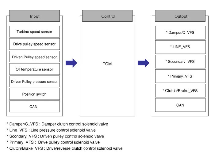
Repair procedures
1.Transmission Control Module (TCM) adaptive values learning : When shift shock has occurred or parts related with the Intelligent Variable Transmission (IVT) has been replaced, TCM learning should be performed.
2.In the following case, TCM learning is required. 1) IVT replacement 2) TCM upgrade or replacement
1.P range learning (learning condition : Intelligent Variable Transmission Fluid (IVTF) temperature : 30 - 90°C (86 - 194°F), shift lever P range, brake off)1) Start the engine after checking for the IVTF temperature in state of IG ON.2) Engine RPM will rise to approximately 1000 rpm after starting the engine.3) After 30 seconds to 2 minutes, the learning is completed when the engine RPM reaches the IDLE level.(Learning completion can be confirmed from the "Sensor Data" of diagnotic tool )

• Do not operate the shift lever, step on the accelerator pedal or brakes during P-step learning.(If it is operated during learning, perform it again after turning off the ignition switch.)
Transmission Control Module (TCM) ➤
E-Module ➤
Driven Pulley Pressure Sensor ➤
Driven Pulley Speed Sensor
| Item | Specification |
| Type | Hall sensor |
| Output voltage (V) | High : 1.18 - 1.68 (Nor : 1.4) |
| Low : 0.59 - 0.84 (Nor : 0.7) |
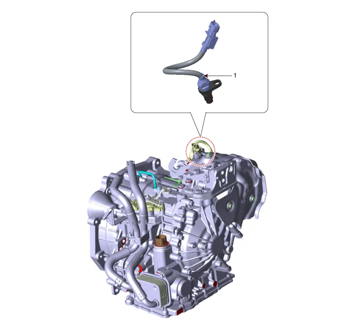
1. Driven pulley speed sensor
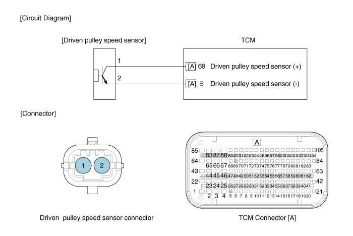
1.Check the sensor waveform with diagnostic tool.
1.Remove the air cleaner assembly.(Refer to Engine Mechanical System - "Air Cleaner")
2.Remove the battery and battery tray. (Refer to Body Electrical System - "Battery")
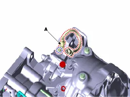
3.Disconnect the driven pulley speed sensor connector (A).
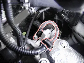
4.Remove the driven pulley speed sensor (A) after loosening the bolt.
Tightening torque:9.8 - 14.7 N.m (1.0 - 1.5 kgf.m, 7.2 - 10.8 lb-ft)
1.To install, reverse the removal procedures.
Position Switch ➤
Shift Lever
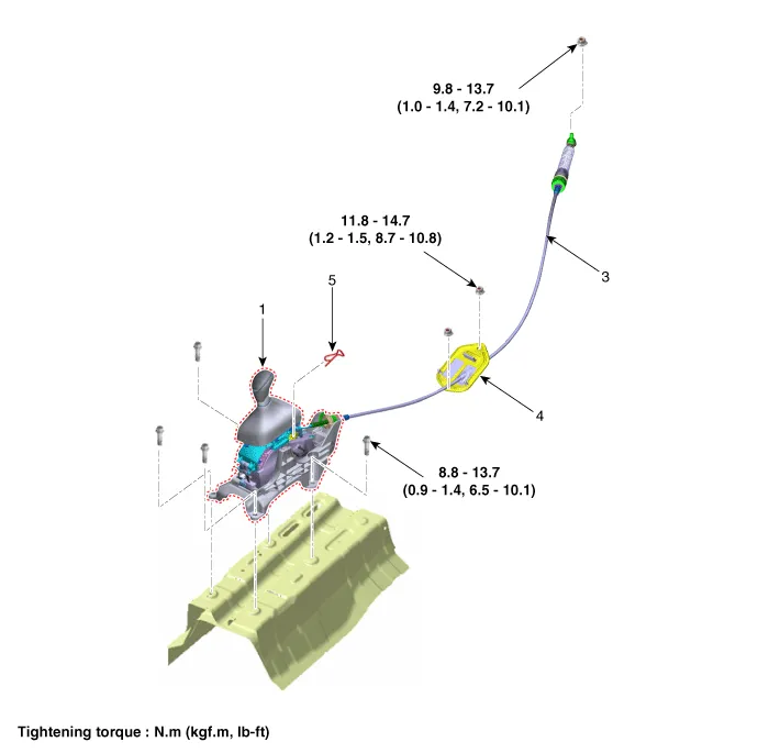
1. Shift lever knob & boots
2. Shift lever assembly
3. Shift cable
4. Shift cable retainer
5. Snap pin
1.Turn ignition switch OFF and disconnect the negative (-) battery cable.
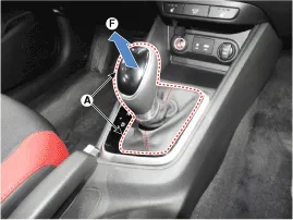
2.Pull the knob & boots (A) in the direction of "F" and remove the knob & boots (A).
3.Remove the floor console.(Refer to Body - "Floor Console")
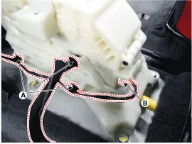
4.Disconnect the fixing clip (A) of wiring and connector (B) from the shift lever.
5.Disconnect the shift cable.
(1)Remove the snap pin (A).
(2)Disconnect the cable eye end (B) from the shift lever.
(3)Disconnect the cable socket (C) from the shift lever.
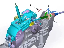

• Lug (A) must assemble upward.
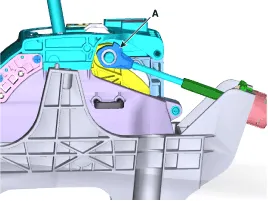
• Bending area (A) must assemble the front.
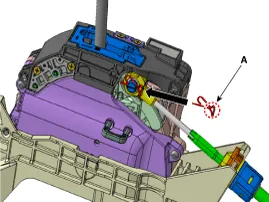
6.Remove the bolts and then shift lever assembly (A).
Tightening torque :8.8 - 13.7 N.m (0.9 - 1.4 kgf.m, 6.5 - 10.1 lb-ft)
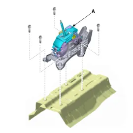
1.To install, reverse the removal procedure.

• Install the cable after placing the shift lever and the manual control lever in the N position.
Shift Cable
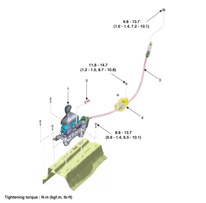
1. Shift lever knob & boots
2. Shift lever assembly
3. Shift cable
4. shift cable retainer
5. Snap pin
1.Remove the air cleaner assembly and air duct.(Refer to Engine Mechanical System - "Air Cleaner")
2.Remove the battery and battery tray.(Refer to Engine Electrical System - "Battery")
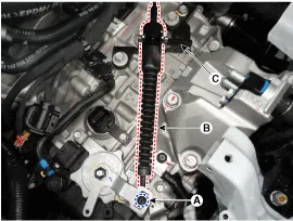
3.Remove the nut (A) from the manual control lever.
4.Remove the shift cable (B) from the bracket (C) at transaxle side.
5.Remove the floor console assembly. (Refer to Body - "Floor Console")
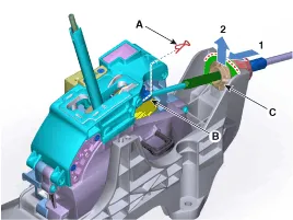
6.Disconnect the shift cable.
(1)Remove the snap pin (A).
(2)Disconnect the cable eye end (B) from the shift lever.
(3)Disconnect the cable socket (C) from the shift lever.
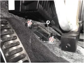
7.Disconnect the shift cable retainer after removing the nuts (A).
8.Remove the shift cable by pulling it toward the interior.
1.Install the shift cable retainer (A).
Tightening torque : 11.8 - 14.7 N.m (1.2 - 1.5 kgf.m, 8.7 - 10.8 lb-ft)
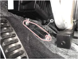

• Install the cable after placing the shift lever and the manual control lever in the N position.
2.Install the shift cable (A) in the shifter lever.
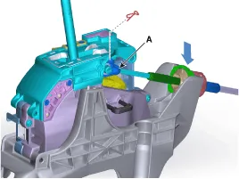

• Lug (A) must assemble upward.
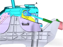
• When assembling the snap pin, be careful about the correct direction. - The band portion (A) must point to the front of the vehicle. - The band portion (A) must point outwards.
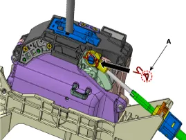
3.Install the shift cable (B) in the cable bracket (C).
4.Align the hole (E) in the manual control lever with the "N" position hole (G) of the inhibitor switch and then insert the inhibitor switch guide pin (SST No: 09480-A3800).
5.Lightly tighten the nut (A) after connected the shift cable (B) in the manual control lever (D).
6.Push the shift cable (B) lightly to "F" direction shown to eliminate free play of shift cable.
7.Tighten the nut (A) to the specified torque.
Tightening torque : 9.8 - 13.7 N.m (1.0 - 1.4 kgf.m, 7.2 - 10.1 lb-ft)
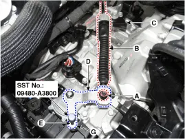
8.Remove the inhibitor switch guide pin (SST No.: 09480-A3800) from the hole.
9.Install the floor console assembly.(Refer to Body - "Floor Console")
10.Install the air cleaner assembly.(Refer to Engine Mechanical System - "Air Cleaner")
11.Install the battery and battery tray.(Refer to Engine Electrical System - "Battery")
12.Install the air duct.(Refer to Engine Mechanical System - "Air Cleaner")
13.Check that operating surely at each range of the position switch corresponding to each position of shift lever.
Parking Sprag
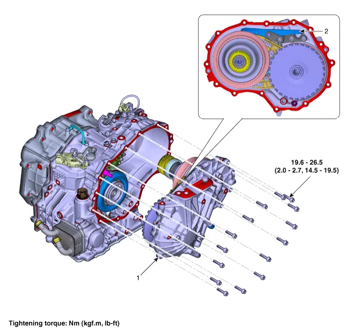
1. Rear housing
2. Parking sprag
1.Set shift lever to N position.
2.Remove the IVTF drain plug allow the fluid to drain out and then reinstall the drain plug.(Refer to Hydraulic System - "Fluid")
3.Remove the Intelligent Variable Transmission (IVT).(Refer to Intelligent Variable Transmission (IVT) System (C0GF1) - "Intelligent Variable Transmission (IVT)")
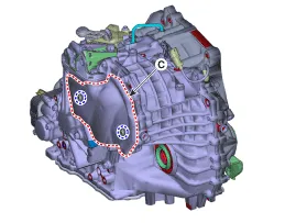
4.Loosen the bolts and then removing the heat protector (A, B, C).
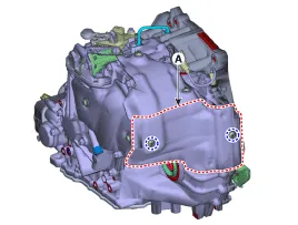
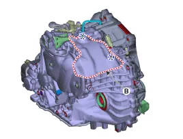
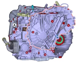
5.Loosen the bolts and then removing the rear housing (A).
Tightening torque : 19.6 - 26.5 N.m (2.0 - 2.7 kgf.m, 14.5 - 19.5 lb-ft)
6.Loosen the bolts and then removing the parking sprag (A) from rear housing.
Tightening torque : 24.5 - 29.4 N.m (2.5 - 3.0 kgf.m, 18.1 - 21.7 lb-ft)
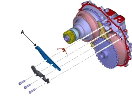

• Before mounting, replace the parking rod cam if there are excessive flaws on the outside of the parking rod cam (A).(Refer to IVT Control System - "Parking Rod Cam")
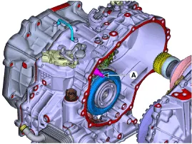
• Make sure that there is an O-ring on the side of the case.
• Remove the old sealant from the mounting surface and apply a new sealant.
1.To install reverse the removal procedures.
2.Injection the IVT fluid.(Refer to Hydraulic System - "Fluid")
Parking Rod Cam
1.Remove the IVTF drain plug allow the fluid to drain out and then reinstall the drain plug.(Refer to Hydraulic System - "Fluid")
2.Remove the Intelligent Variable Transmission (IVT).(Refer to Intelligent Variable Transmission (IVT) System (C0GF1) - "Intelligent Variable Transmission (IVT)")
3.Remove the torque convertor (A) from convertor housing.
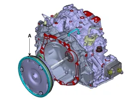
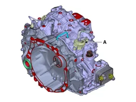
4.Loosen the bolts and nut and then removing the position switch (A).
Tightening torque : Manual lever mounting nut : 17.7 - 24.5 N.m (1.8 - 2.5 kgf.m, 13.0 - 18.1 lb-ft) Position switch mounting bolt : 9.8 - 11.8 N.m (1.0 - 1.2 kgf.m, 7.2 - 8.7 lb-ft)
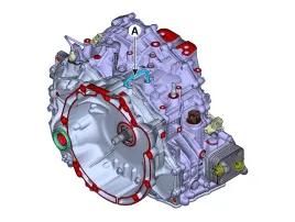
5.Loosen the bolts and then removing the tube (A).
Tightening torque : 9.8 - 11.8 N.m (1.0 - 1.2 kgf.m, 7.2 - 8.7 lb-ft)
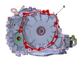
6.Loosen the bolts and then removing the torque convertor (A).
Tightening torque : 27.5 - 34.3 N.m (2.8 - 3.5 kgf.m, 20.1 - 25.3 lb-ft)
7.Loosen the bolt and then removing the manual guide (A).
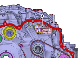
8.Loosen the bolts (A) and then removing the manual shaft (B).
Tightening torque : 9.8 - 11.8 N.m (1.0 - 1.2 kgf.m, 7.2 - 8.7 lb-ft)
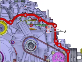
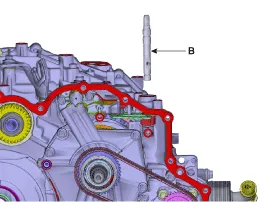
9.Remove the parking rod assembly (A) in the "F" direction.
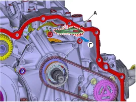
10.Remove the parking rod cam (A) from parking rod assembly.
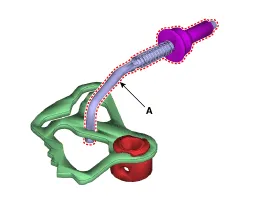

• Remove the old sealant from the mounting surface and apply a new sealant.
1.To install reverse the removal procedures.
2.Injection the IVT fluid.(Refer to Hydraulic System - "Fluid")
Other information:
Hyundai Accent (HC) (2017 - 2022) Service Manual: Brake Line
- Components [Disc Type] [Drum Type] - Removal [Brake Tube (Engine Room)] 1.Disconnect the negative (-) battery cable. 2.Disconnect the brake fluid level switch connector. 3.Remove the brake fluid from the master cylinder reservior with a syringe. • Do not spill brake fluid on the vehicle, it may damage the paint; if brake fluid does contact the paint, wash it off immediately with water.Hyundai Accent (HC) (2017 - 2022) Service Manual: Alternator
- Specification ItemSpecification Rated voltage13.5V, 130A Speed in use 1,000 - 18,000 rpm Voltage regulatorIC Regulator built-in type Regulator Setting VoltageExternal mode 10.6 - 16 ± 0.3V Internal mode14.5 ± 0.3V Temperature GradientExternal mode0 ± 2 mV / °C Internal mode-3.5 ± 2 mV / °C - Description The Alternator has eight built-in diodes, each rectifying AC current to DC current.
Contents
- Description and Operation
- Repair procedures
- Transmission Control Module (TCM)
- E-Module
- Driven Pulley Pressure Sensor
- Driven Pulley Speed Sensor
- Position Switch
- Shift Lever
- Shift Cable
- Parking Sprag
- Parking Rod Cam
Categories
- Manuals Home
- Hyundai Accent Owners Manual
- Hyundai Accent Service Manual
- New on site
- Most important about car


