Hyundai Accent: Engine Mechanical System / Engine And Transaxle Assembly
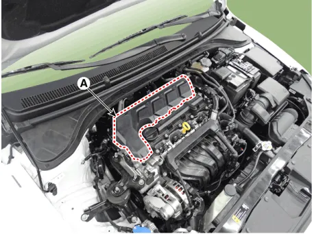
Engine Cover
1.Remove the engine cover (A).
2.Installation is reverse order of removal
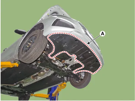
Engine Room Under Cover
1.Remove the engine room under cover (A).
Tightening torque :7.8 - 11.8 N.m (0.8 - 1.2 kgf.m, 5.8 - 8.7 lb-ft)
2.Installation is reverse order of removal.
Engine Mounting
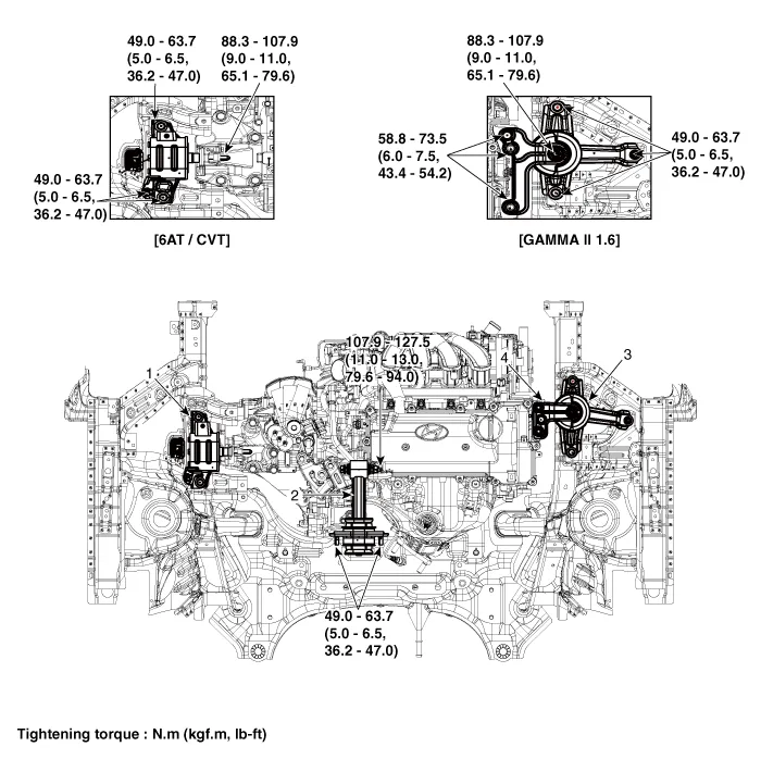
1. Transaxle mounting bracket
2. Roll road bracket
3. Engine mounting bracket
4. Engine mounting support bracket
1.Remove the engine room under cover.(Refer to Engine and Transaxle Assembly - "Engine Room Under Cover")
2.Install the jack to the edge of oil pan
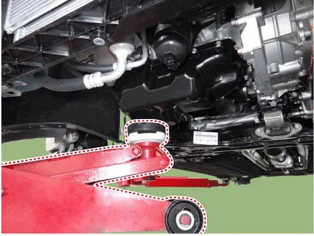

• Insert the rubber block between jack and oil pan.
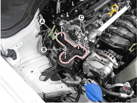
3.Remove the engine mounting support bracket (A).
Tightening torque Nut (B) : 88.3 - 107.9 N.m (9.0 - 11.0 kgf.m, 65.1 - 79.6 lb-ft)Bolt, Nuts (C) : 58.8 - 73.6 N.m (6.0 - 7.5 kgf.m, 43.4 - 54.2 lb-ft)
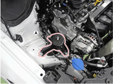
4.Remove the engine mounting bracket (A).
Tightening torque :49.0 - 63.7 N.m (5.0 - 6.5 kgf.m, 36.2 - 47.0 lb-ft)
5.Install in the reverse order of removal.
1.Disconnect the battery negative terminal.
2.Remove the engine room under cover.(Refer to Engine and Transaxle Assembly - "Engine Room Under Cover")
3.Remove the air duct and air cleaner assembly.(Refer to Intake and Exhaust System - "Air Cleaner")
4.Remove the battery.(Refer to Engine Electrical System - "Battery")
5.Remove the engine control module (ECM).(Refer to Engine Control/Fuel System - "Engine Control Module (ECM)")
6.Remove the battery tray.(Refer to Engine Electrical System - "Battery")
7.Install the jack under the transaxle to support it.
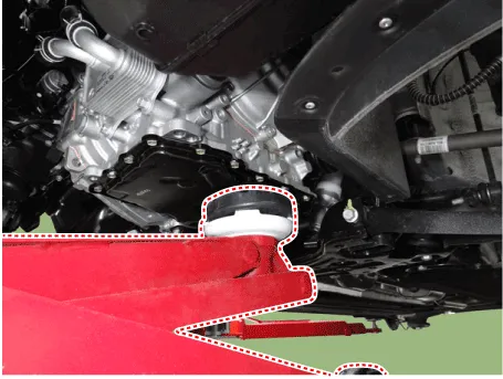

• Insert the rubber block between jack and transaxle.
8.Remove the service cover (A).
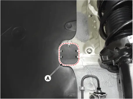
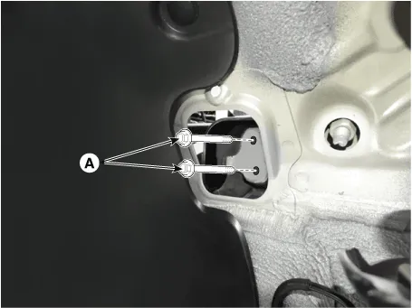
9.Remove the transaxle support bracket mounting bolts (A).
Tightening torque :88.3 - 107.9 N.m (9.0 - 11.0 kgf.m, 65.1 - 79.6 lb-ft)
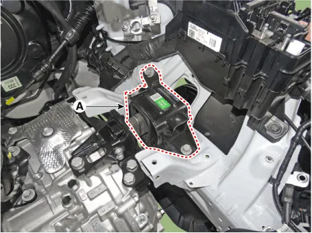
10.Remove the transaxle mounting bracket (A).
Tightening torque : 49.0 - 63.7 N.m (5.0 - 6.5 kgf.m, 36.2 - 47.0 lb-ft)
11.Install in the reverse order of removal.
1.Remove the engine room under cover.(Refer to Engine and Transaxle Assembly - "Engine Room Under Cover")
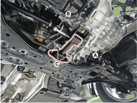
2.Remove the roll rod bracket (A).
Tightening torqueBolt (B) : 107.9 - 127.5 N.m (11.0 - 13.0 kgf.m, 79.6 - 94.0 lb-ft)Bolts (C) : 49.0 - 63.7 N.m (5.0 - 6.5 kgf.m, 36.2 - 47.0 lb-ft)
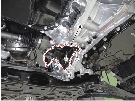
3.Remove the roll rod suppot bracket (A).
Tightening torque :49.0 - 68.6 N.m (5.0 - 7.0 kgf.m, 36.2 - 50.6 lb-ft)
4.Install in the reverse order of removal.
Engine And Transaxle Assembly ➤
Other information:
Hyundai Accent (HC) (2017 - 2022) Service Manual: Specifications
- Specifications Transaxle typeM6CF1 Engine typeGasoline 1.6 MPI Gear ratio1st3.769 2nd2.045 3rd1.370 4th1.036 5th0.794 6th0.688 Reverse3.700 Final gear ratio4.267 - Tightening Torques ItemsN.mkgf.mlb-ft Oil drain plug58.9 - 78.56.0 - 8.043.4 - 57.8 Oil filler plug58.9 - 78.56.0 - 8.043.4 - 57.8 Shift lever assembly bolt8.8 - 13.Hyundai Accent (HC) (2017 - 2022) Service Manual: SRS Control Module (SRSCM)
- Description • Supplemental Restraint System Control Module (SRSCM) determines whether and when to deploy air bag module, seat belt pretensioner (BPT). • It supplies the air bag module with the power required to deploy the module or the BPT. • It also performs self-diagnosis function of the supplemental restraint system. - Components 1.
Contents
Categories
- Manuals Home
- Hyundai Accent Owners Manual
- Hyundai Accent Service Manual
- New on site
- Most important about car


