Hyundai Accent: Engine Control / Fuel System / Engine Control System
Components and Components Location ➤
Description and Operation ➤
Engine Control Module (ECM) ➤
Mass Air Flow Sensor (MAFS)
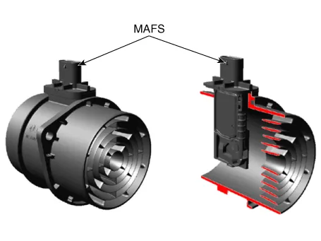

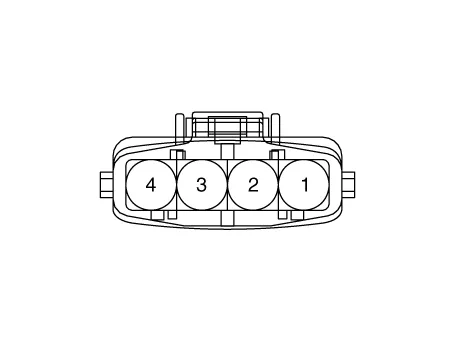

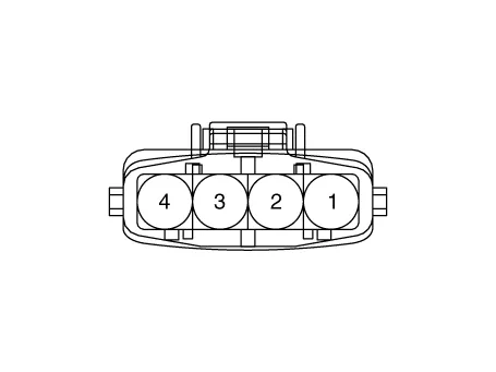
1.Check the MAFS visually.
– Mounting direction correct.
– Any contamination, corrosion or damage on connector.
– Air cleaner's clogging or wet.
– MAFS cylinder's deforming or blocking by any foreign material.
2.Check any leakage on intake system and intercooler system.
1.Turn the ignition switch OFF and disconnect the battery (-) cable.
2.Disconnect the MAFS connector (A).
3.Remove the clamp (B).
4.Remove the installation bolts and then remove the MAFS (C).
Mass air flow sensor clamp installation bolt :2.9 - 4.9 N.m (0.3 - 0.5 kgf.m, 2.2 - 3.6 lb-ft)Mass air flow sensor installation bolt :2.9 - 4.9 N.m (0.3 - 0.5 kgf.m, 2.2 - 3.6 lb-ft)
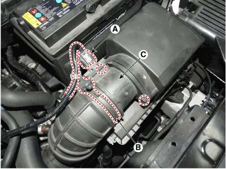

• Install the component with the specified torques.
• Note that internal damage may occur when the component is dropped. In this case, use it after inspecting.

• Be careful not to damage the sensing element and the honey cell.
1.Install in the reverse order of removal.
ETC (Electronic Throttle control) System ➤
Manifold Absolute Pressure Sensor (MAPS)
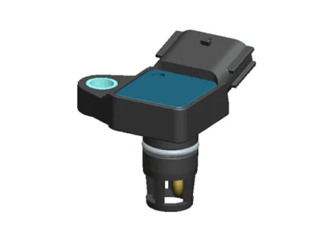
| Pressure (kPa) | Output Voltage (V) |
| 10 | 0.5 |
| 62.5 | 2.5 |
| 115 | 4.5 |
1.Connect a GDS on Data Link Connector (DLC).
2.Check MAPS output voltage at idle and IG ON.
| Condition | Output Voltage (V) |
| IG ON | 3.9 ~ 4.1 |
| Idle | 0.8 ~ 1.6 |
1.Turn the ignition switch OFF and disconnect the battery negative (-) cable.
2.Disconnect the manifold absolute pressure sensor connector (A).
3.Remove the installation bolt (B), and then remove the sensor from the surge tank.
Manifold absolute pressure sensor installation bolt :6.9 ~ 8.8 N.m (0.7 ~ 0.9 kgf.m, 5.1 ~ 6.5 lb-ft)
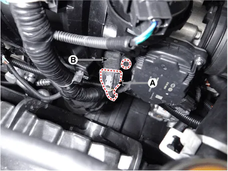

• Install the component with the specified torques.
• Note that internal damage may occur when the component is dropped. In this case, use it after inspecting.

• Insert the sensor in the installation hole and be careful not to damage when installation.
1.Install in the reverse order of removal.
Intake Air Temperature Sensor (IATS)
| Temperature [°C (°F)] | Resistance (kΩ) |
| -40 (-40) | 38.88 ~ 50.77 |
| -20 (-4) | 13.19 ~ 16.82 |
| 0 (32) | 5.11 ~ 6.11 |
| 20 (68) | 2.19 ~ 2.69 |
| 40 (104) | 1.02 ~ 1.26 |
| 60 (140) | 0.51 ~ 0.64 |
| 80 (176) | 0.27 ~ 0.35 |
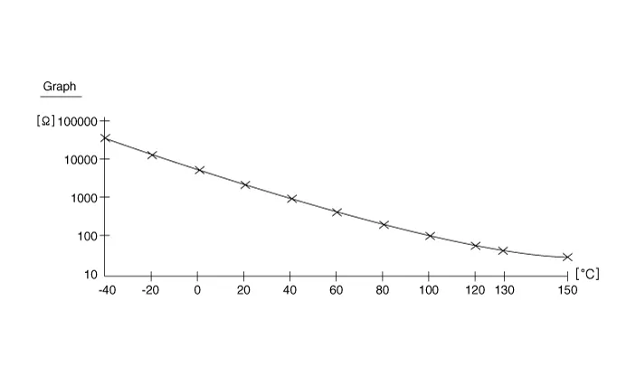
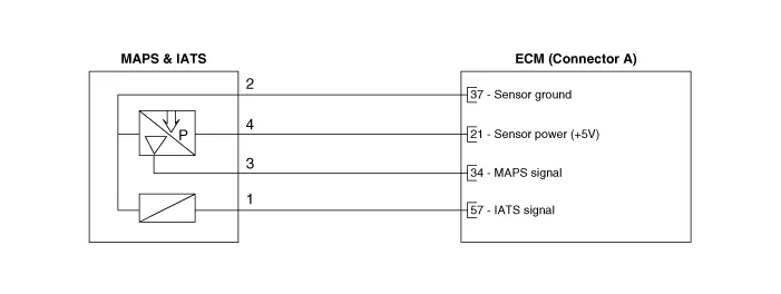
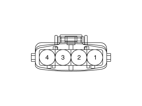
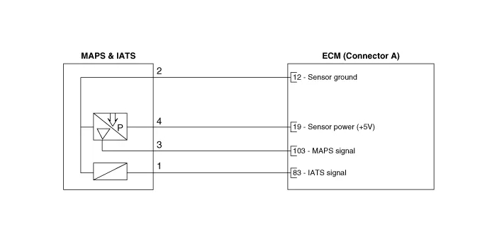
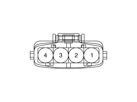
1.Turn ignition switch OFF.
2.Disconnect IATS connector.
3.Measure resistance between IATS terminals 3 and 4.
4.Check that the resistance is within the specification.
Specification : Refer to "Specification"
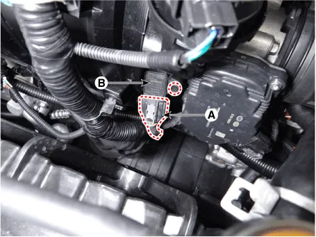
1.Turn the ignition switch OFF and disconnect the battery negative (-) cable.
2.Disconnect the manifold absolute pressure sensor connector (A).
3.Remove the installation bolt (B), and then remove the sensor from the surge tank.
Manifold absolute pressure sensor installation bolt :6.9 ~ 8.8 N.m (0.7 ~ 0.9 kgf.m, 5.1 ~ 6.5 lb-ft)

• Install the component with the specified torques.
• Note that internal damage may occur when the component is dropped. In this case, use it after inspecting.

• Insert the sensor in the installation hole and be careful not to damage when installation.
1.Install in the reverse order of removal.
Engine Coolant Temperature Sensor (ECTS) ➤
Crankshaft Position Sensor (CKPS)
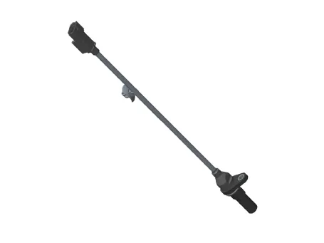
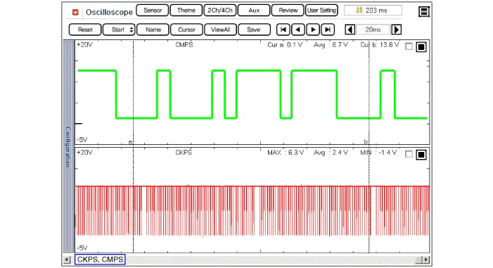
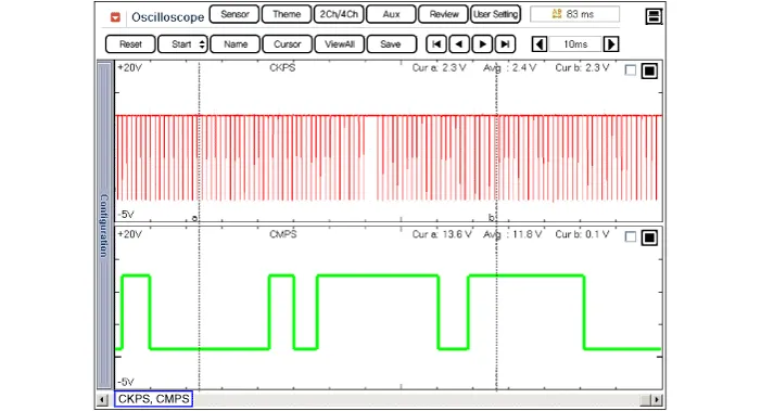
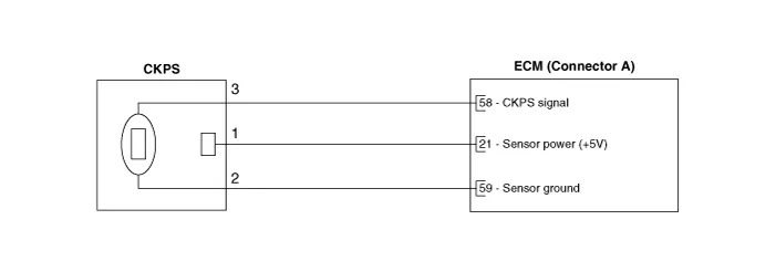

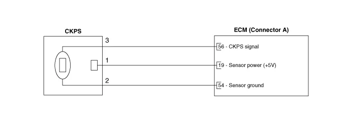

1.Check signal waveform of CKPS and CMPS using a GDS.
Specification : Refer to "Waveform"
1.Turn the ignition switch OFF and disconnect the battery negative (-) cable.
2.Remove the engine room under cover.(Refer to Engine and Transaxle Assembly - "Engine Room Under Cover")
3.Disconnect the crankshaft position sensor connector (A).
4.Remove the installation bolt (B), and then remove the crankshaft position sensor.
Crankshaft position sensor installation bolt :7.8 ~ 11.8 N.m (0.8 ~ 1.2 kgf.m, 5.8 ~ 8.7 lb-ft)
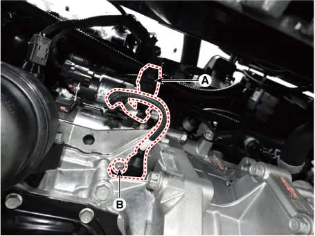

• Install the component with the specified torques.
• Note that internal damage may occur when the component is dropped. If the component has been dropped, inspect before installing.

• Apply the engine coolant to the O-ring.

• Insert the sensor in the installation hole and be careful not to damage.
1.Install in the reverse order of removal.
Camshaft Position Sensor (CMPS)
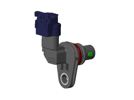
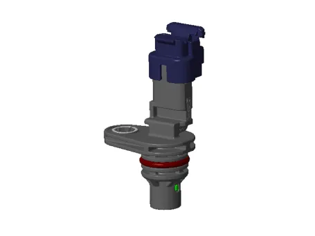
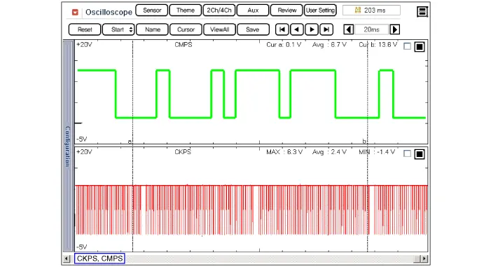
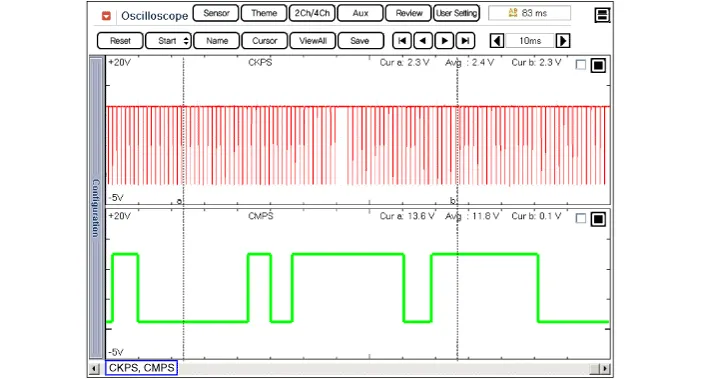
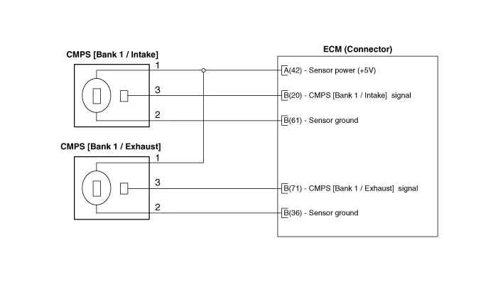


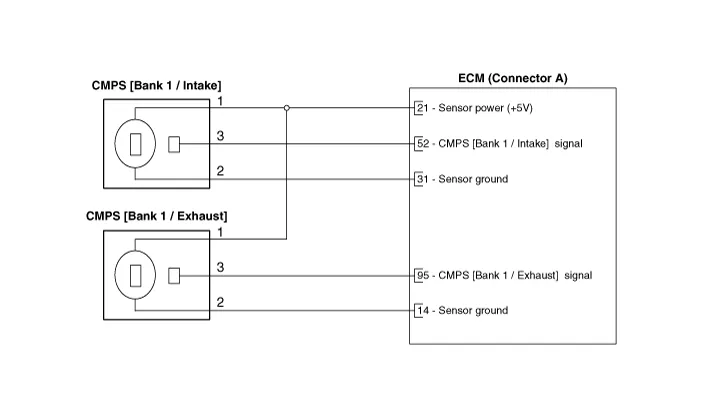


1.Check signal waveform of CKPS and CMPS using a scan tool.
Specification : Refer to "Waveform"

• DON’T remove the camshaft position sensor during engine running or right after engine stops, or a scald by the flowed out engine oil may occur.
1.Turn the ignition switch OFF and disconnect the battery negative (-) cable.
2.Disconnect the camshaft position sensor connector (A).
3.Remove the installation bolt, and then remove the sensor (B).
Camshaft position sensor installation bolt :7.8 ~ 11.8 N.m (0.8 ~ 1.2 kgf.m, 5.8 ~ 8.7 lb-ft)
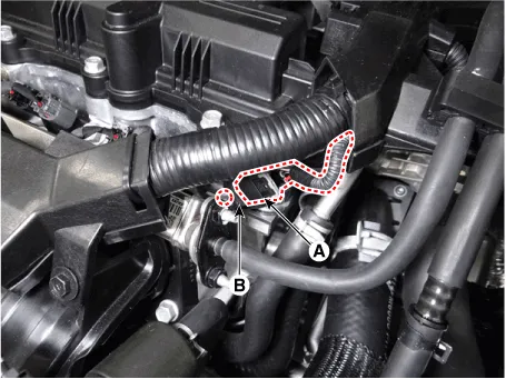
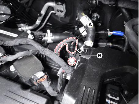
1.Turn the ignition switch OFF and disconnect the battery negative (-) cable.
2.Disconnect the camshaft position sensor connector (A).
3.Remove the installation bolt, and then remove the sensor (B).
Camshaft position sensor installation bolt :7.8 ~ 11.8 N.m (0.8 ~ 1.2 kgf.m, 5.8 ~ 8.7 lb-ft)

• Install the component with the specified torques.
• Note that internal damage may occur when the component is dropped. If the component has been dropped, inspect before installing.

• Apply the engine coolant to the O-ring.

• Insert the sensor in the installation hole and be careful not to damage.
1.Install in the reverse order of removal.
Knock Sensor (KS)
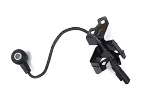
| Item | Specification | Remarks |
| Capacitance (pF) | 850 ~ 1150 | 1 Khz |
| Insulation registance (MΩ) | 850 ~ 1150 | Pin to Body |

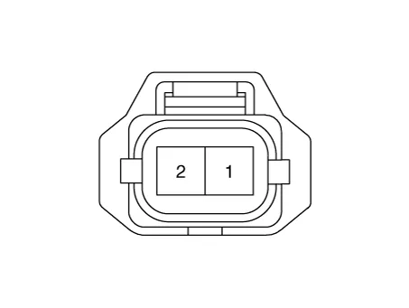
1.Turn the ignition switch OFF and disconnect the battery negative (-) cable.
2.Remove the intake manifold.(Refer to Engine Mechanical System - "Intake Manifold")
3.Remove the installation bolt (A), and then remove the sensor from the cylinder block.
Knock sensor installation bolt :18.6 ~ 24.5 N.m (1.9 ~ 2.5 kgf.m, 13.7 ~ 18.1 lb-ft)
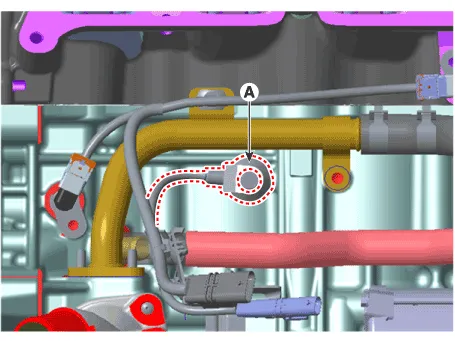

• Install the component with the specified torques.
• Note that internal damage may occur when the component is dropped. In this case, use it after inspecting.
1.Install in the reverse order of removal.
Heated Oxygen Sensor (HO2S) ➤
Accelerator Position Sensor (APS)
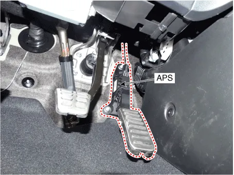
| Items | Specification | |
| APS 1 | APS 2 | |
| C.T | 0.7 ~ 0.8 | 0.33 ~ 0.43 |
| W.O.T | 4.13 ~ 4.22 | 2.04 ~ 2.13 |
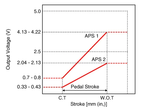
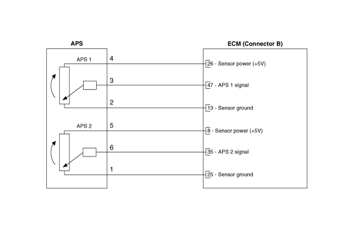
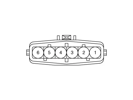
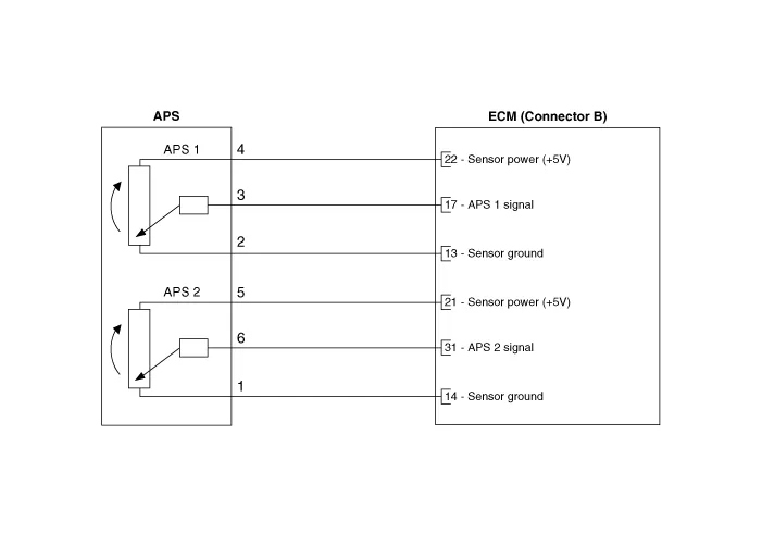
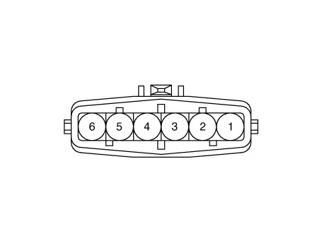
1.Connect the GDS on the Diagnosis Link Connector (DLC).
2.Start engine and check output voltages of APS 1 and 2 at C.T and W.O.T.
Specification : Refer to Specification Section.
Fuel Tank Pressure Sensor (FTPS) ➤
Injector ➤
Purge Control Solenoid Valve (PCSV)
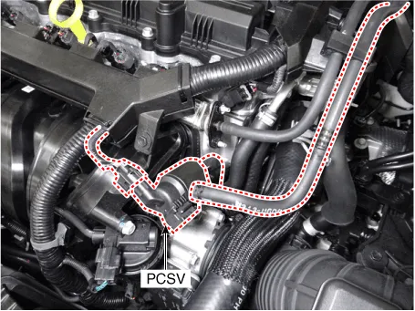
| Item | Specification |
| Coil Resistance (Ω) | 12.5 ~ 16.5 [20°C (68°F)] |

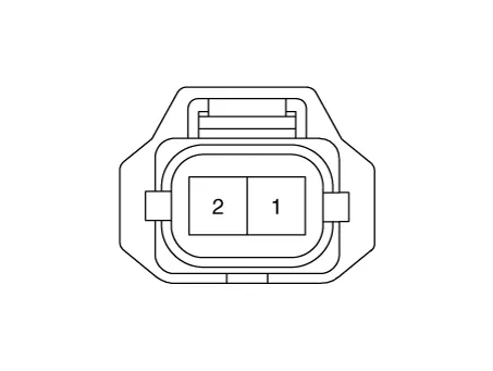

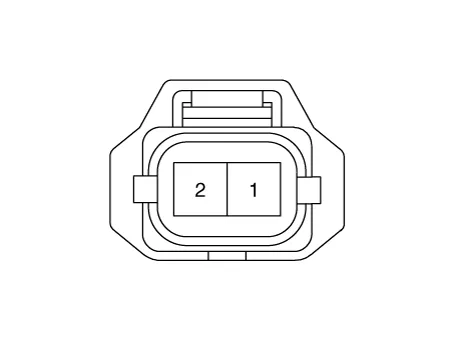
1.Turn ignition switch OFF.
2.Disconnect PCSV connector.
3.Measure resistance between PCSV terminals 1 and 2.
4.Check that the resistance is within the specification.
| Item | Specification |
| Coil Resistance (Ω) | 12.5 ~ 16.5 [20°C (68°F)] |
1.Turn the ignition switch OFF and disconnect the battery negative (-) cable.
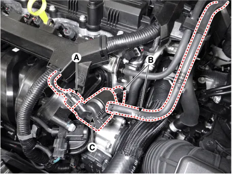
2.Disconnect the purge control solenoid valve connector (A).
3.Disconnect the vapor hoses (B).
4.Remove the purge control solenoid valve (C).

• Install the component with the specified torques.
• Note that internal damage may occur when the component is dropped. In this case, use it after inspecting.

• Be careful of foreign material not to flow into the valve.
1.Install in the reverse order of removal.
CVVT Oil Control Valve (OCV)
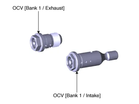
1.When camshaft rotates engine rotation-wise: Intake-Advance / Exhaust-Retard
2.When camshaft rotates counter engine rotation-wise: Intake- Retard / Exhaust- Advance
1.Turn ignition switch OFF.
2.Disconnect OCV connector.
3.Measure resistance between OCV terminals 1 and 2.
4.Check that the resistance is within the specification.
Specification : Refer to "Specification"
1.Turn the ignition switch OFF and disconnect the battery negative (-) cable.
2.Remove the cylinder head cover.(Refer to Engine Mechanical System - "Cylinder Head Cover")
3.When reomve the oil control valve, hold the hexagonal portion on the camshaft with a wrench to prevent the camshaft from rotating.
4.Remove the CVVT oil control valve (A).
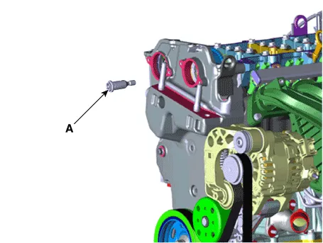
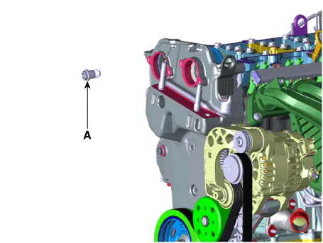
1.Install in the reverse order of removal.
Variable Force Solenoid (VFS) ➤
Variable Intake Solenoid (VIS) Valve ➤
Electric EGR Control Valve ➤
Canister Close Valve (CCV)
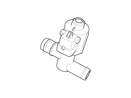
| Item | Specification |
| Coil Resistance (Ω) | 19.8 - 20.8 [20°C (68°F)] |


1.Turn the ignition switch OFF.
2.Disconnect the CCV connector.
3.Measure resistance between the CCV terminal 1 and 2.
4.Check that the resistance is within the specification.
Specification : Refer to "Specification"
5.Disconnect the vapor hose connected with the canister from the CCV.
6.Connect a vacuum pump to the nipple.
7.Ground the CCV control line and apply battery voltage to the CCV power supply line.
8.Apply vacuum and check the valve operation.
Specification : Vacuum maintained
1.Turn the ignition switch OFF and disconnect the battery negative (-) cable.
2.Lift the vehicle.
3.Disconnect the canister close velve extension connector (A).
4.Remove the canister protector (B).
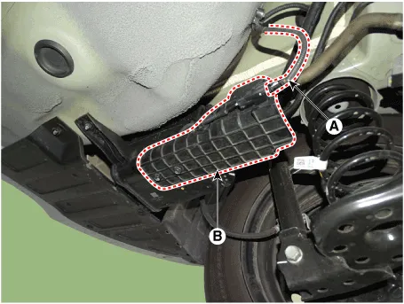
5.Disconnect the canister close velve connector (A).
6.Remove the ventilation hose (B).
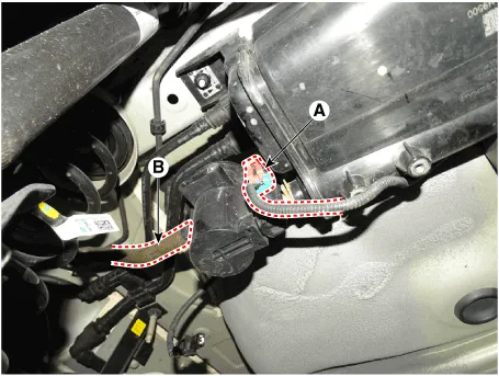
7.Remove the air filter (A).
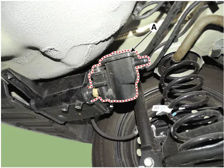
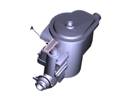
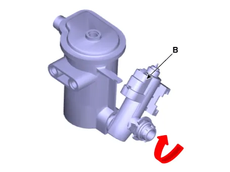
8.Release the lever (A), and then separate the canister close valve (B) from the fuel tank air filter after rotating it in the direction of the arrow in the figure.

• Install the component with the specified torques.
• Note that internal damage may occur when the component is dropped. In this case, use it after inspecting.
1.Install in the reverse order of removal.
Thermal Management Module (TMM) Motor
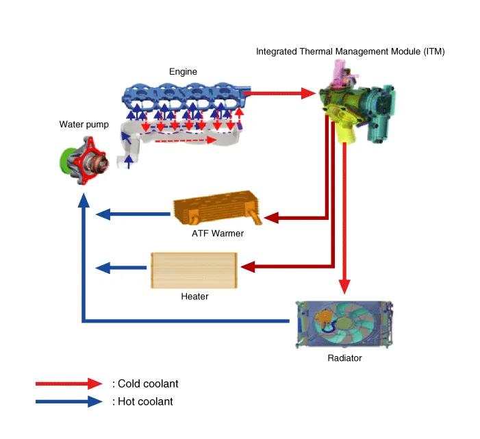
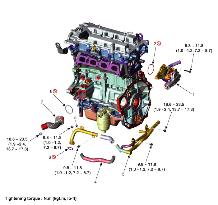
1. Integrated thermal management module (ITM)
2. Integrated thermal management module (ITM) O-ring
3. Heater pipe B
4. Heater water hose
5. Heater pipe A
6. Heater pipe A gasket
7. Water inlet fitting
8. Water inlet fitting gasket
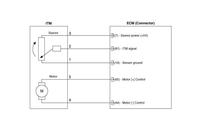

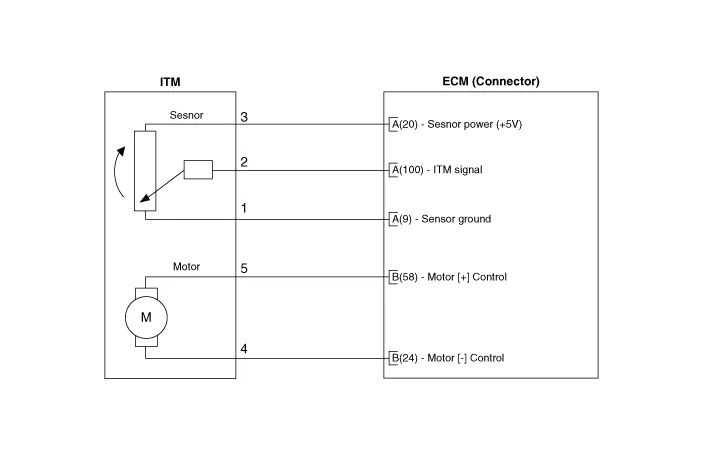

1.Remove the integrated thermal management module (ITM).(Refer to Engine Mechanical System - "Integrated Thermal Management Module (ITM)")

• A separate replacement of the ITM (Integrated Thermal Management Motor) is not possible. You should place the new ITM (Integrated Thermal Management Module) assembly to fix the problem.
1.Install in the reverse order of removal.

• A separate replacement of the ITM (Integrated Thermal Management Motor) is not possible. You should place the new ITM (Integrated Thermal Management Module) assembly to fix the problem.
Other information:
Hyundai Accent (HC) (2017 - 2022) Service Manual: Front Hub / Knuckle
- Components 1. Brake disc2. Front hub3. Hub bearing4. Dust cover5. Front axle6. Snap ring - Removal 1.Loosen the wheel nuts slightly.Raise the vehicle, and make sure it is securely supported. 2.Remove the front wheel and tire (A) from the front hub.Tightening torque :107.9 - 127.5 N.m (11.0 - 13.0 kgf.m, 79.6 - 94.0 lb-ft) • Be careful not to damage the hub bolts when removing the front wheel and tire.Hyundai Accent (HC) (2017 - 2022) Service Manual: Troubleshooting
- Troubleshooting Limp Home Mode Limp Home Mode features a fail-safe function that prevents dangerous situations in the event of a transmission failure. The vehicle will be driven in limp home mode if the transmission malfunctions. In this mode, the transmission operates at a minimal functionality level (fixed shifting, limited shifting, reverse, neutral), making it possible for the vehicle to reach a service center.
Contents
- Components and Components Location
- Description and Operation
- Engine Control Module (ECM)
- Mass Air Flow Sensor (MAFS)
- ETC (Electronic Throttle control) System
- Manifold Absolute Pressure Sensor (MAPS)
- Intake Air Temperature Sensor (IATS)
- Engine Coolant Temperature Sensor (ECTS)
- Crankshaft Position Sensor (CKPS)
- Camshaft Position Sensor (CMPS)
- Knock Sensor (KS)
- Heated Oxygen Sensor (HO2S)
- Accelerator Position Sensor (APS)
- Fuel Tank Pressure Sensor (FTPS)
- Injector
- Purge Control Solenoid Valve (PCSV)
- CVVT Oil Control Valve (OCV)
- Variable Force Solenoid (VFS)
- Variable Intake Solenoid (VIS) Valve
- Electric EGR Control Valve
- Canister Close Valve (CCV)
- Thermal Management Module (TMM) Motor
Categories
- Manuals Home
- Hyundai Accent Owners Manual
- Hyundai Accent Service Manual
- New on site
- Most important about car


