Hyundai Accent (HC): Body (Interior and Exterior) / Crash Pad
Contents:
- Components and Components Location
- Cluster Fascia Panel
- Crash Pad Lower Panel
- Steering Column Shroud Panel
- Crash Pad Side Cover
- Glove Box Upper Cover Housing
- Main Crash Pad Assembly
- Cowl Cross Bar Assembly
Components and Components Location
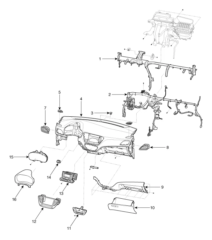
1. Cowl cross bar assembly
2. Crash pad main wiring harness
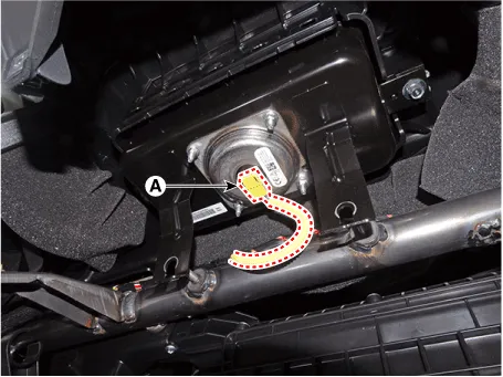
3. Poto sensor
4. Main crash pad assembly
5. Side defroster nozzle [LH]
6. Side defroster nozzle [RH]
7. Side air vent duct [LH]
8. Side air vent duct [RH]
9. Glove box upper cover housing
10. Glove box
11. Heater & A/C control unit
12. Center fascia panel
13. Audio assembly
14. Hazard swich
15. Cluster guide assembly
16. Cluster fascia panel
Cluster Fascia Panel
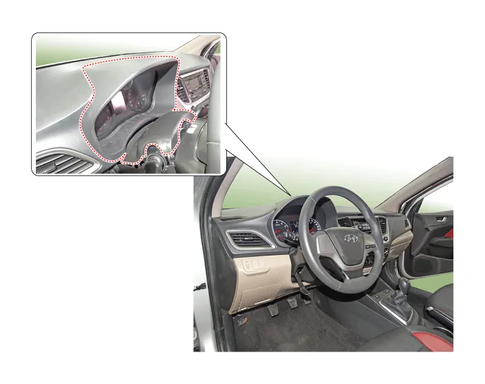
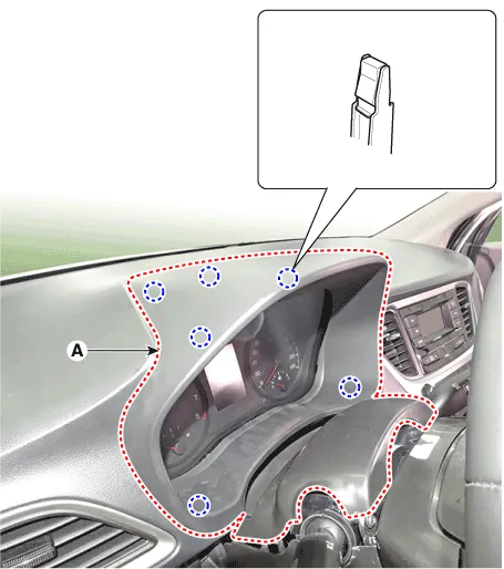
1. Cluster fascia panel

• Put on gloves to prevent hand injuries.

• When removing with a flat - tip screwdriver or remover, wrap protective tape around the tools to prevent damage to components.
• Use a plastic panel removal tool to remove interior trim pieces without marring the surface.
• Take care not to bend or scratch the trim and panels.
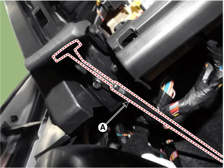
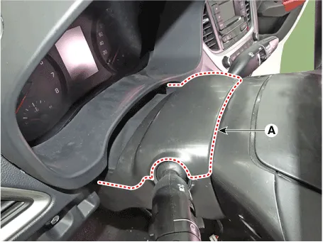
1.Using a screwdriver or remover, remove the steering column shroud upper panel (A).

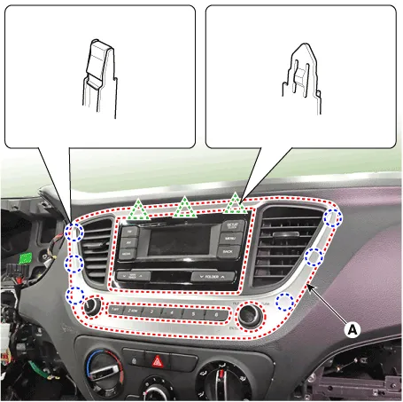
2.Using a screwdriver or remover, remove the cluster fascia panel (A).

3.To install, reverse the removal procedure.

• Make sure the connector are connected in properly.
• Replace any damaged clips (or pin - type retainers).
Crash Pad Lower Panel

• Put on gloves to prevent hand injuries.

• When removing with a flat - tip screwdriver or remover, wrap protective tape around the tools to prevent damage to components.
• Use a plastic panel removal tool to remove interior trim pieces without marring the surface.
• Take care not to bend or scratch the trim and panels.
1.Remove the cowl side trim.(Refer to Interior Trim - "Cowl Side Trim")
2.Using a screwdriver or remover, remove the crash pad side cover [LH] (A).
3.Remove the fuse box cover (A).
4.Disconnect the hood latch release handle cable (A).
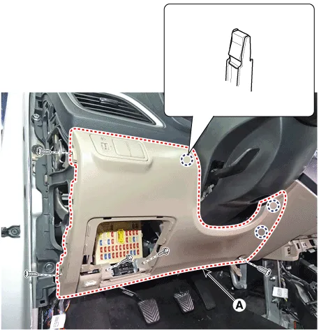
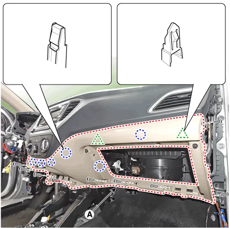
5.Loosen the mounting screws and remove the crash pad lower panel (A).
6.Disconnect the connector (A).
7.To install, reverse the removal procedure.

• Make sure the connector are connected in properly.
• Replace any damaged clips (or pin - type retainers).
Steering Column Shroud Panel
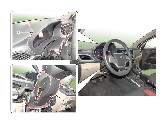
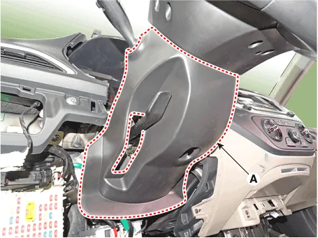
1. Steering column shroud lower panel
2. Steering column shroud upper panel

• Put on gloves to prevent hand injuries.

• When removing with a flat - tip screwdriver or remover, wrap protective tape around the tools to prevent damage to components.
• Use a plastic panel removal tool to remove interior trim pieces without marring the surface.
• Take care not to bend or scratch the trim and panels.
1.Using a screwdriver or remover, remove the steering column shroud upper panel (A).
2.Using a screwdriver or remover, remove the cluster fascia panel (A).
3.To install, reverse the removal procedure.

• Replace any damaged clips (or pin - type retainers).

• Put on gloves to prevent hand injuries.

• When removing with a flat - tip screwdriver or remover, wrap protective tape around the tools to prevent damage to components.
• Use a plastic panel removal tool to remove interior trim pieces without marring the surface.
• Take care not to bend or scratch the trim and panels.
1.Remove the crash pad lower panel.(Refer to Crash Pad - "Crash Pad Lower Panel")
2.Loosen the mounting screws by turning the steering wheel to the left and right, and remove the steering column shroud lower panel (A).
3.To install, reverse the removal procedure.

• Replace any damaged clips (or pin - type retainers).
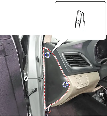
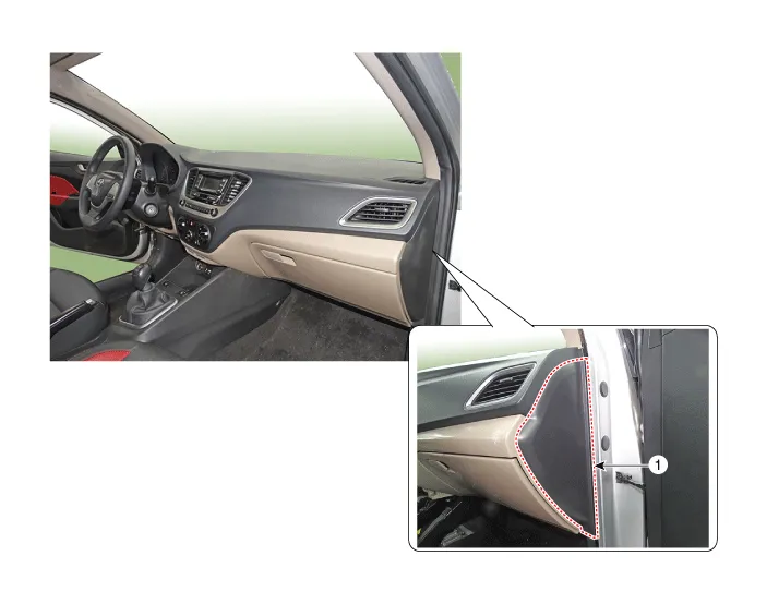
Crash Pad Side Cover
[LH]
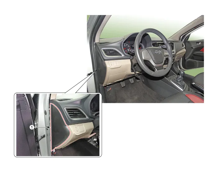
1. Crash pad side cover [LH]
[RH]
1. Crash pad side cover [RH]

• Put on gloves to prevent hand injuries.

• When removing with a flat - tip screwdriver or remover, wrap protective tape around the tools to prevent damage to components.
• Use a plastic panel removal tool to remove interior trim pieces without marring the surface.
• Take care not to bend or scratch the trim and panels.
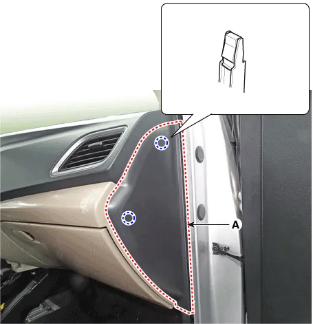
1.Using a screwdriver or remover, remove the crash pad side cover (A).[LH]

2.To install, reverse the removal procedure.

• Replace any damaged clips (or pin - type retainers).
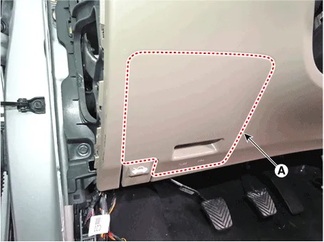
Glove Box Upper Cover Housing
1. Glove box upper cover housing

• Put on gloves to prevent hand injuries.

• When removing with a flat - tip screwdriver or remover, wrap protective tape around the tools to prevent damage to components.
• Use a plastic panel removal tool to remove interior trim pieces without marring the surface.
• Take care not to bend or scratch the trim and panels.
1.Remove the floor console.(Refer to Floor Console - "Floor Console Assembly")
2.Remove the cowl side trim.(Refer to Interior Trim - "Cowl Side Trim")
3.Open the glove box (A) in the direction of the arrow.
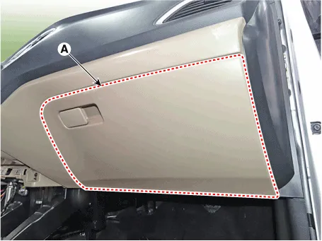
4.Press both sides of the stoppers (B) down the glove box (A).
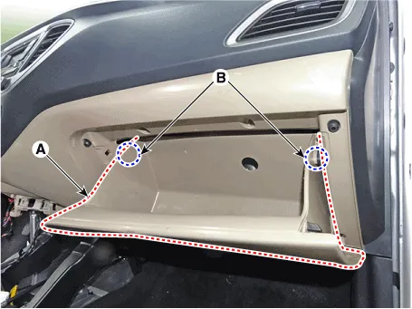
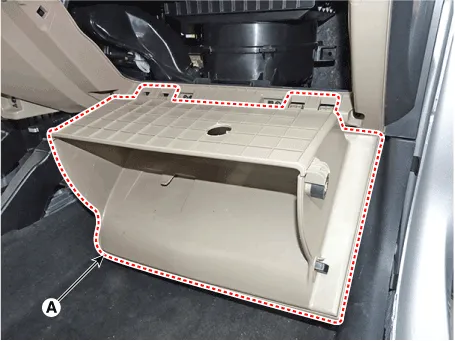
5.Remove the glove box (A).
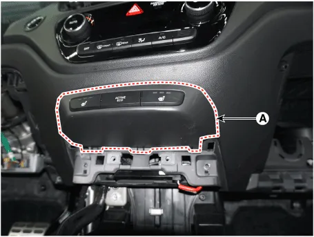
6.Using a screwdriver or remover, remove the crash pad side cover [RH] (A).

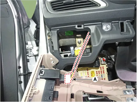
7.Using a screwdriver or remover, remove the crash pad lower switch complete (A).
8.Disconnect the crash pad lower switch complete connector (A).
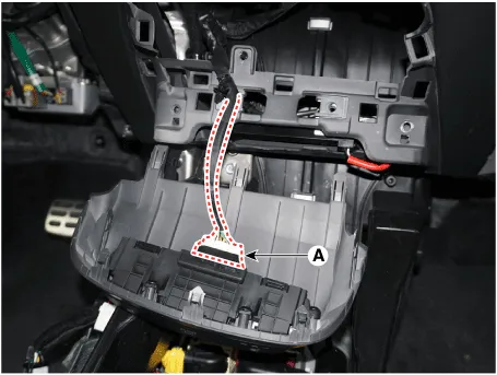
9.After loosening the mounting screws remove the glove box upper cover assembly (A).
10.To install, reverse the removal procedure.

• Make sure the connector are connected in properly.
• Replace any damaged clips (or pin - type retainers).
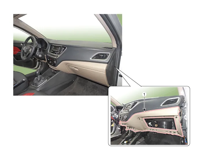
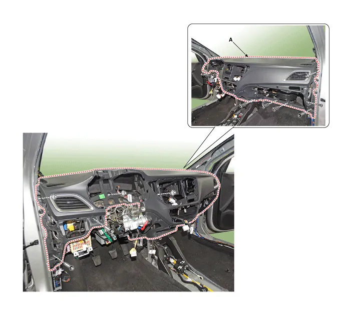
Main Crash Pad Assembly
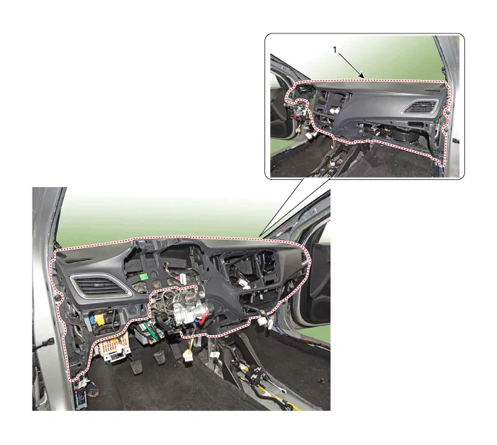
1. Main crash pad assembly

• Put on gloves to prevent hand injuries.

• When removing with a flat - tip screwdriver or remover, wrap protective tape around the tools to prevent damage to components.
• Use a plastic panel removal tool to remove interior trim pieces without marring the surface.
• Take care not to bend or scratch the trim and panels.
1.Disconnect the negative ( - ) battery terminal.
2.Remove the front pillar trim.(Refer to Interior Trim - "Front Pillar Trim")
3.Remove the floor console assembly.(Refer to Floor Console - "Floor Console Assembly")
4.Remove the crash pad lower panel.(Refer to Crash Pad - "Crash Pad Lower Panel")
5.Remove the cluster fascia panel.(Refer to Cluster Pad - "Center Fascia Panel")
6.Remove the heater & A/C control unit .(Refer to Heating,Ventilation and Air Conditioning - "Heater & A/C Control Unit (MANUAL)") (Refer to Heating,Ventilation and Air Conditioning - "Heater & A/C Control Unit (DATC)")
7.Remove the glove box upper cover housing assembly.(Refer to Crash Pad - "Glove Box Upper Cover Housing")
8.Remove the steering wheel.(Refer to Steering System - "Steering Wheel")
9.Remove the steering column shroud lower panel.(Refer to Crash Pad - "Steering Column Shroud Panel")
10.Remove the multifunction switch assembly.(Refer to Body Electrical System - "Multifunction Switch")
11.Remove the instrument cluster.(Refer to Body Electrical System - "Instrument Cluster")
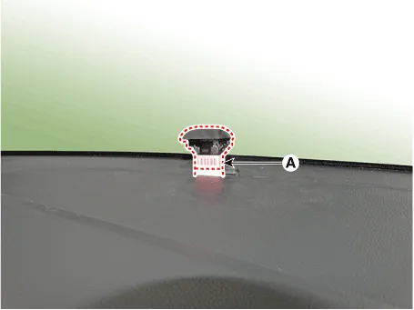
12.Disconnect the security lamp connector (A).
13.Using a screwdiriver or remover, remove the crash pad fascia panel (A).
14.Loosen the mounting nuts (A).
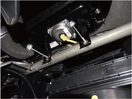
15.Disconnect the passenger's airbag connectors (A).
16.Loosen the mounting bolts and nuts and remove the main crash pad assembly (A).
17.To install, reverse the removal procedure.

• Make sure the crash pad fits onto the guide pins correctly.
• Before tightening the bolts, make sure the crash pad wire harnesses are not pinched.
• Make sure the connectors are plugged in properly, and the antenna lead is connected properly.
• Make sure that each of the assembly components operates properly.
• Replace any damaged clips (or pin - type retainers).
Cowl Cross Bar Assembly
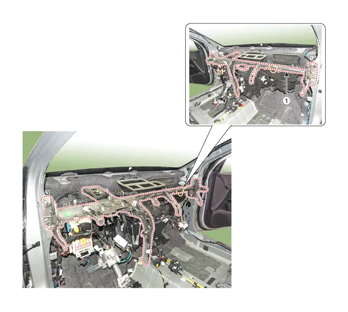
1. Cowl cross bar assembly

• Put on gloves to prevent hand injuries.

• When removing with a flat - tip screwdriver or remover, wrap protective tape around the tools to prevent damage to components.
• Use a plastic panel removal tool to remove interior trim pieces without marring the surface.
• Take care not to bend or scratch the trim and panels.
1.Disconnect the negative ( - ) battery terminal.
2.Recover the refrigerant with a recovery/recycling/charging station.
3.Remove the cowl top cover.(Refer to "Cowl Top Cover")
4.Disconnect the steering column connectors.(Refer to Steering System - "Steering Column and Shaft")
5.Loosen the mounting nuts and through bolts in the frontal area and lower the steering column.(Refer to Steering System - "Steering Column and Shaft")
6.Disconnect the expansion valve from the evaporator core.(Refer to Heating,Ventilation and air Conditioning - "Heater Unit")
7.Disconnect the inlet and outlet heater hoses from the heater unit.(Refer to Heating,Ventilation and air Conditioning - "Heater Unit")
8.Remove both sides of front seat assembly.(Refer to Front Seat - "Front Seat Assembly")
9.Remove the main crash pad assembly.(Refer to Crash Pad - "Main Crash Pad Assembly")
10.Remove the shift lever assembly.(Refer to Manual Transaxle System - "Shift lever") (Refer to Automatic Transaxle System - "Shift lever")
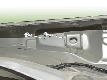
11.Loosen the cowl cross bar mounting bolts.
Tightening torque : 16.7 - 25.5 N.m (1.7 - 2.6 kgf.m, 12.3 -18.8 lb-ft)
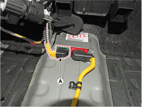
12.Disconnect the airbag control module (SRSCM) connector (A).
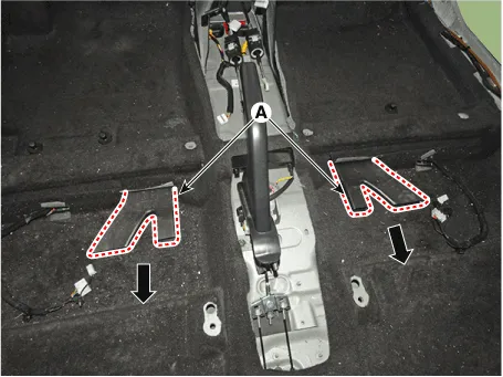
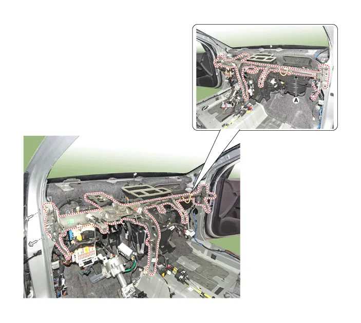
13.Remove the rear air duct (A)
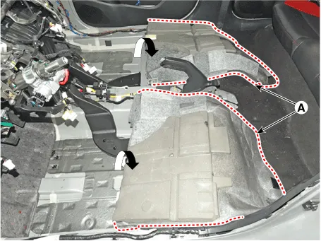
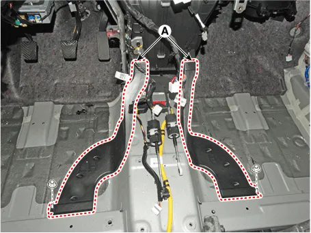
14.Separate the floor carpet (A) to obtain space for removing the rear heating duct.
15.Loosen the mounting nuts and remove the front air duct (A).
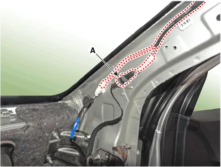
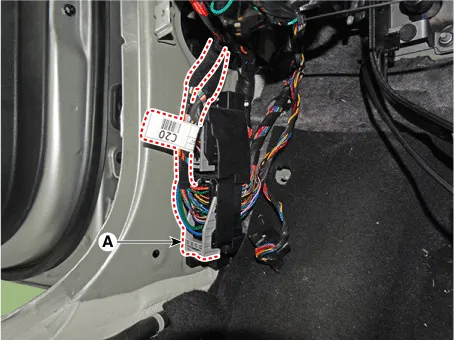
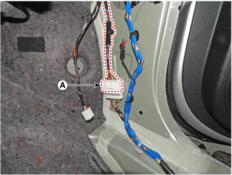
16.Disconnect the connector (A) and the mounting wiring fasteners in the front pillar.
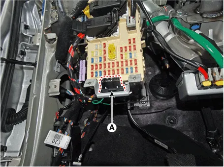
17.Disconnect the diagnosis connector (A).
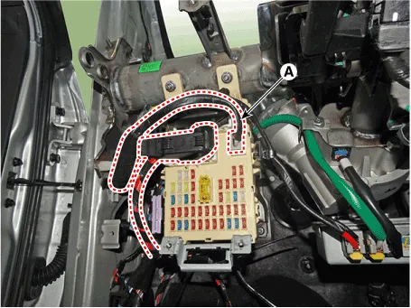
18.Disconnect the passenger compartment junction box connectors (A).
19.Disconnect the multi box connectors (A).[Driver's]
20.Disconnect the heater and blower unit connector.
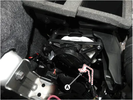
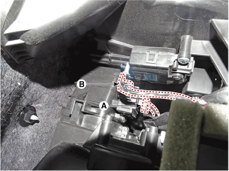
(1)Disconnect the mode actuator connector (A).
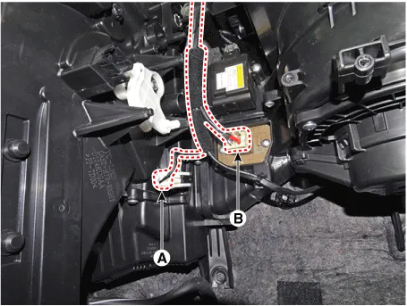
(2)Disconnect the evaporator temperature sensor (A), and power mosfet (B).
(3)Disconnect the cluster ionizer (A) and intake actuator connector (B).
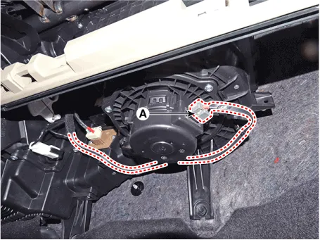
(4)Disconnect the blower motor connector (A).
21.After loosening the bolts and nuts, remove the cowl cross bar assembly (A).
22.To install, reverse the removal procedure.

• Make sure the crash pad fits onto the guide pins correctly.
• Before tightening the bolts, make sure the crash pad wire harnesses are not pinched.
• Make sure the connectors are plugged in properly, and the antenna lead is connected properly.
• Enter the anti- theft code for the radio, then enter the customer`s radio station presets.
• Make sure that each of the assembly components operates properly.
• Replace any damaged clips (or pin - type retainers).


Other information:

Contents
- Components and Components Location
- Cluster Fascia Panel
- Crash Pad Lower Panel
- Steering Column Shroud Panel
- Crash Pad Side Cover
- Glove Box Upper Cover Housing
- Main Crash Pad Assembly
- Cowl Cross Bar Assembly
Categories
- Manuals Home
- Hyundai Accent Owners Manual
- Hyundai Accent Service Manual
- Questions & Answers
- Video Guides
- Useful Resources
- New on site
- Most important about car
- Privacy Policy

0.0062