Hyundai Accent (HC): Body (Interior and Exterior) / Floor Console
Contents:
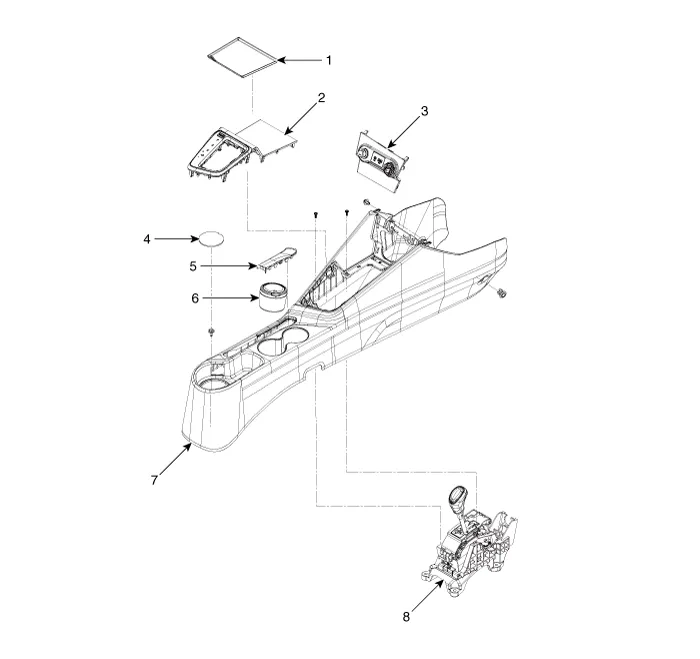
Components and Components Location
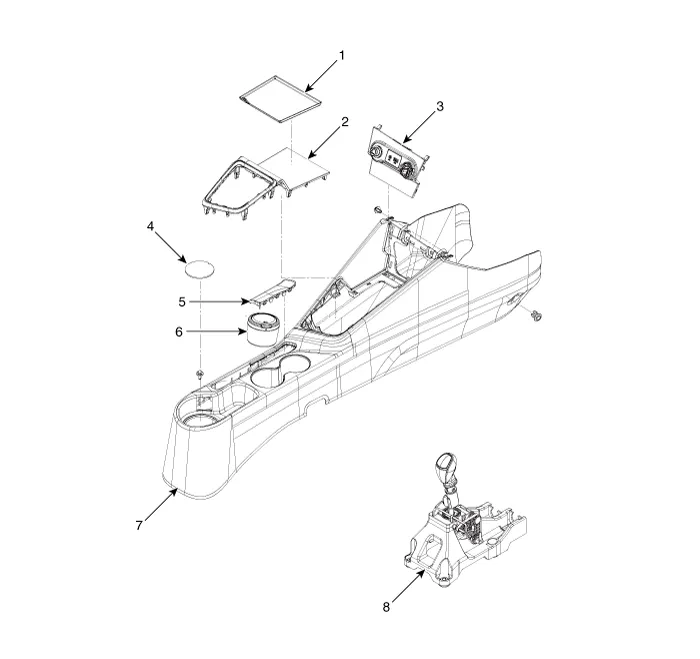
1. Console front tray mat
2. Floor console upper cover
3. Floor console front bazel assembly
4. Console rear tray mat
5. Parking brake cover
6. Portable ashtray
7. Floor console assembly
8. Shift lever
1. Console front tray mat
2. Floor console upper cover
3. Floor console front bazel assembly
4. Console rear tray mat
5. Parking brake cover
6. Portable ashtray
7. Floor console assembly
8. Shift lever
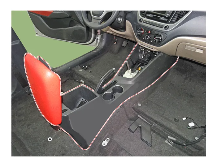
Floor Console Assembly

• Put on gloves to prevent hand injuries.

• When removing with a flat - tip screwdriver or remover, wrap protective tape around the tools to prevent damage to components.
• Use a plastic panel removal tool to remove interior trim pieces without marring the surface.
• Take care not to bend or scratch the trim and panels.
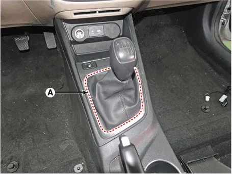
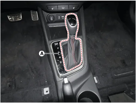
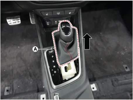
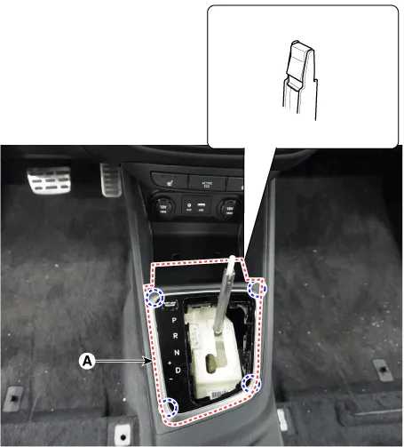
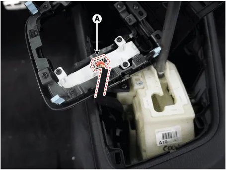
1.Disconnect the gear boots (A).
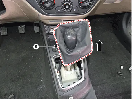
2.Remove the gear knob & boots (A) pull both of it up.
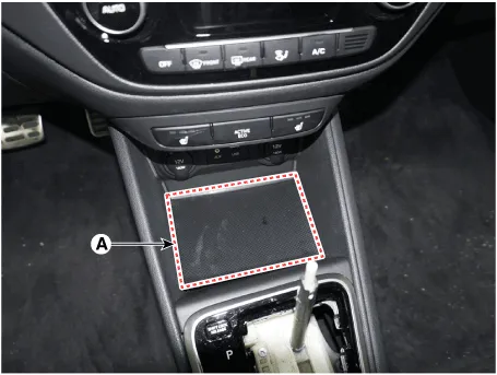
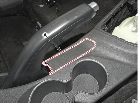
3.Remove the console front tray mat (A).
4.Using a screwdriver or remover, remove the parking brake cover (A).

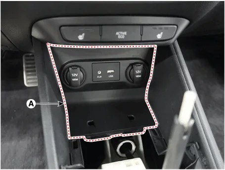
5.Using a screwdriver or remover, remove the console upper cover (A).
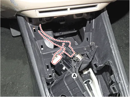
6.Disconnect the connector (A).
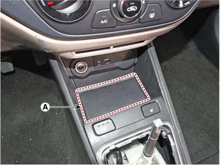
7.Remove the floor console front bezel (A) by pulling it rearward.

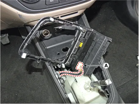
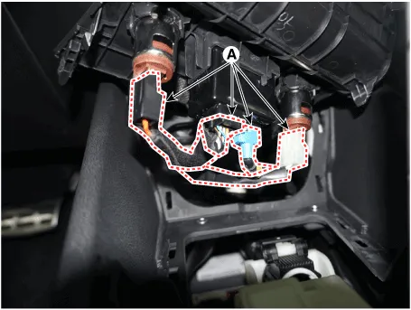
8.Disconnect the connectors (A).
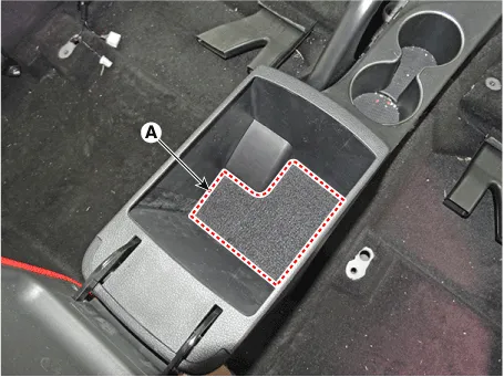
9.Remove the rear console tray mat (A).

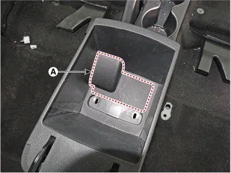
10.Remove the console rear mounting hole cap (A).

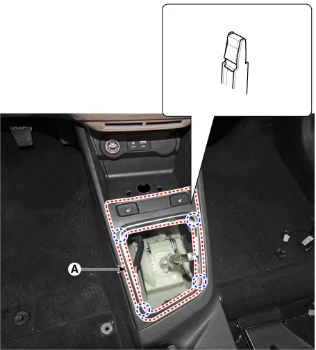
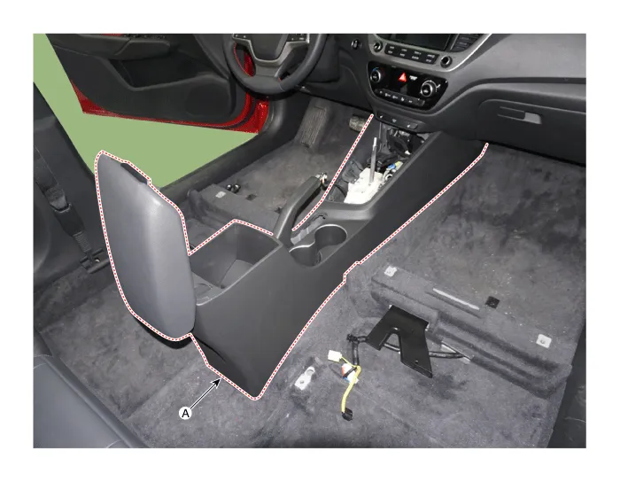
11.After loosening the mounting screws and bolts, remove the console rear complete assembly (A).
12.To install, reverse the removal procedure.

• Make sure the connector is connected properly.
• Replace any damaged clips (or pin - type retainers).

• Put on gloves to prevent hand injuries.

• When removing with a flat-tip screwdriver or remover, wrap protective tape around the tools to prevent damage to components.
• Use a plastic panel removal tool to remove interior trim pieces without marring the surface.
• Take care not to bend or scratch the trim and panels.
1.To remove the gear knob & gear boots (A) pull both of it up.
2.Remove the console front tray mat (A).
3.Using a screwdriver or remover, remove the console upper cover (A).
4.Disconnect the connector (A).
5.Remove the floor console front bezel (A) by pulling it rearward.
6.Disconnect the connectors (A).
7.Using a screwdriver or remover, remove the parking brake cover (A).
8.Remove the rear console tray mat (A).
9.Remove the consol7e rear mounting hole cap (A).
10.After loosening the mounting screws and bolts, remove the console complete assembly (A).
11.To install, reverse removal procedure.

• Make sure the connector is connected properly.
• Replace any damaged clips (or pin - type retainers).
Rear Console Cover
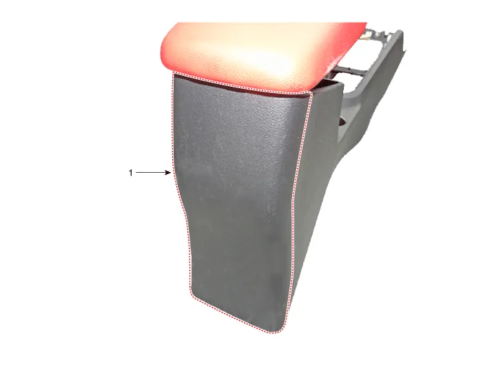
1. Rear console cover

• Put on gloves to prevent hand injuries.

• When removing with a flat - tip screwdriver or remover, wrap protective tape around the tools to prevent damage to components.
• Use a plastic panel removal tool to remove interior trim pieces without marring the surface.
• Take care not to bend or scratch the trim and panels.
1.Remove the floor console assembly.(Refer to Floor Console - "Floor Console Assembly")
2.Loosen the rear console mounting screws.
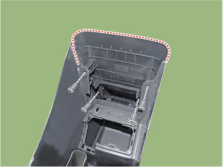
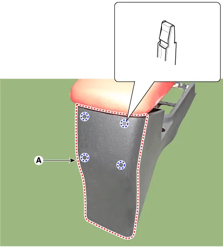
3.Using a screwdriver or remover, remove the rear console cover (A).
4.To install, reverse the removal procedure.

• Make sure the connector is connected properly.
• Replace any damaged clips (or pin - type retainers).
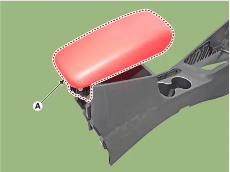
Console Armrest
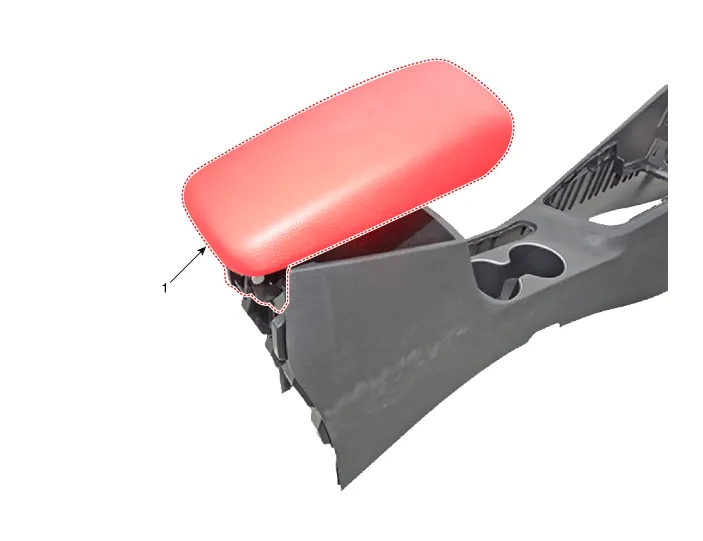
1. Console armrest

• Put on gloves to prevent hand injuries.

• When removing with a flat - tip screwdriver or remover, wrap protective tape around the tools to prevent damage to components.
• Use a plastic panel removal tool to remove interior trim pieces without marring the surface.
• Take care not to bend or scratch the trim and panels.
1.Remove the floor console assembly.(Refer to Floor Console - "Floor Console Assembly")
2.Remove the rear console cover.(Refer to Floor Console - "Rear Console Cover")
3.Loosen the mounting screws and remove the console armrest (A).
4.To install, reverse the removal procedure.

• Replace any damaged clips (or pin - type retainers).


Other information:
Hyundai Accent (HC) (2017 - 2022) Service Manual: Repair procedures
- Refrigerant System Service Basics Refrigerant Identification • Do not mix R-1234yf in the vehicle with other refrigerant, such as R-134a and etc. • Use only service equipment that is U.L-listed and is certified to meet the requirements of SAE standards to recover and recycle R-1234yf from the air conditioning system. Do not use service equipment for the other refrigerant, such as R-134a and etc.Hyundai Accent (HC) (2017 - 2022) Service Manual: Maintenance services
You should exercise the utmost care to prevent damage to your Hyundai Accent and injury to yourself whenever performing any maintenance or inspection procedures. Use proper tools, keep the engine compartment clean, and never work near moving parts with the engine running. Have your vehicle maintained and repaired by an authorized HYUNDAI dealer. An authorized HYUNDAI dealer meets HYUNDAI's high service quality standards and receives technical support from HYUNDAI in order to provide you with a high level of service satisfaction.
Contents
Categories
- Manuals Home
- Hyundai Accent Owners Manual
- Hyundai Accent Service Manual
- Questions & Answers
- Video Guides
- Useful Resources
- New on site
- Most important about car
- Privacy Policy

0.0058