Hyundai Accent (HC): Body (Interior and Exterior) / Floor Console
Contents:
Components and Components Location
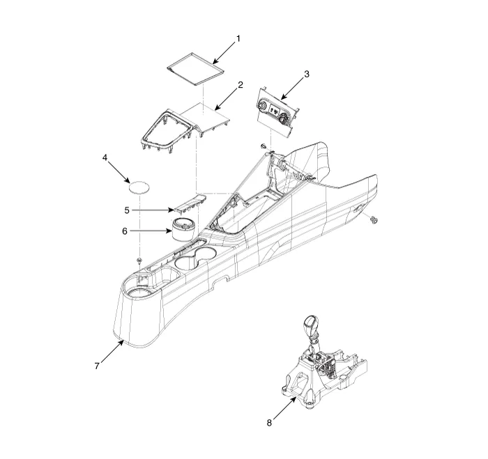
1. Console front tray mat
2. Floor console upper cover
3. Floor console front bazel assembly
4. Console rear tray mat
5. Parking brake cover
6. Portable ashtray
7. Floor console assembly
8. Shift lever
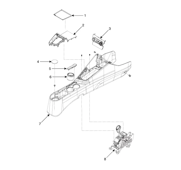
1. Console front tray mat
2. Floor console upper cover
3. Floor console front bazel assembly
4. Console rear tray mat
5. Parking brake cover
6. Portable ashtray
7. Floor console assembly
8. Shift lever
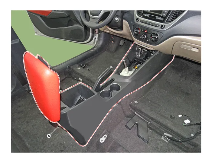
Floor Console Assembly

• Put on gloves to prevent hand injuries.

• When removing with a flat - tip screwdriver or remover, wrap protective tape around the tools to prevent damage to components.
• Use a plastic panel removal tool to remove interior trim pieces without marring the surface.
• Take care not to bend or scratch the trim and panels.
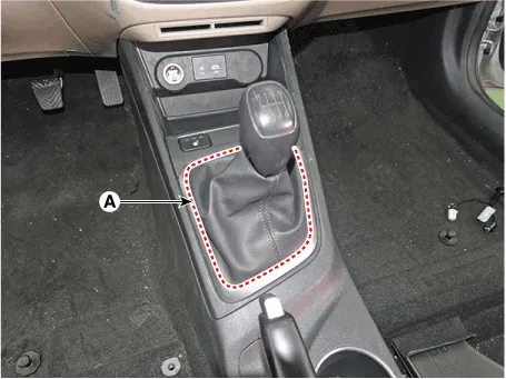
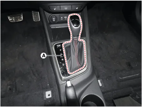
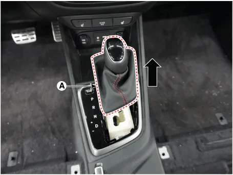
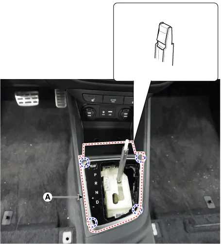
1.Disconnect the gear boots (A).
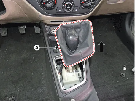
2.Remove the gear knob & boots (A) pull both of it up.
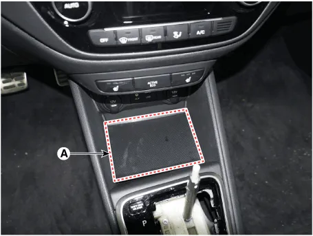
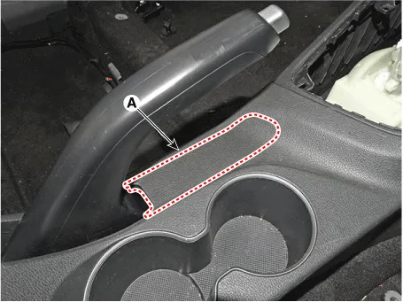
3.Remove the console front tray mat (A).
4.Using a screwdriver or remover, remove the parking brake cover (A).

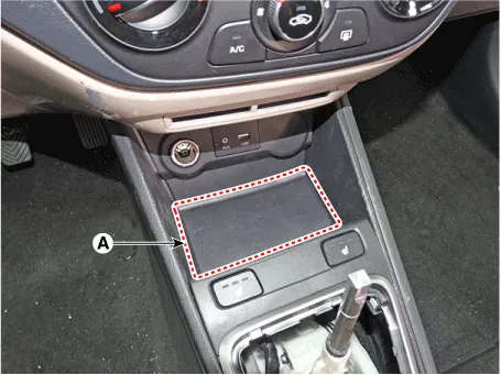
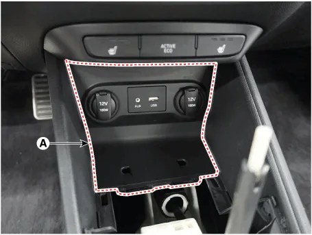
5.Using a screwdriver or remover, remove the console upper cover (A).
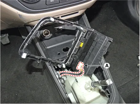
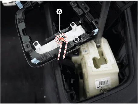
6.Disconnect the connector (A).
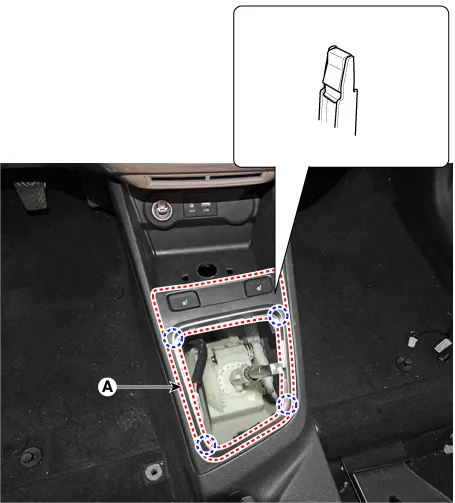
7.Remove the floor console front bezel (A) by pulling it rearward.

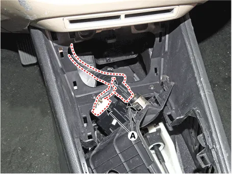
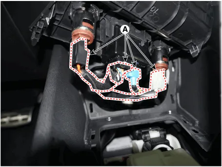
8.Disconnect the connectors (A).
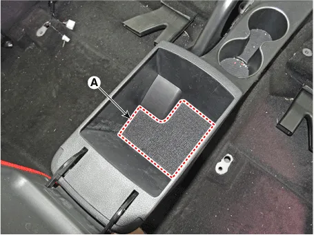
9.Remove the rear console tray mat (A).

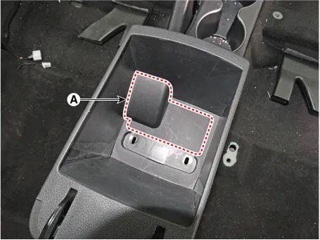
10.Remove the console rear mounting hole cap (A).

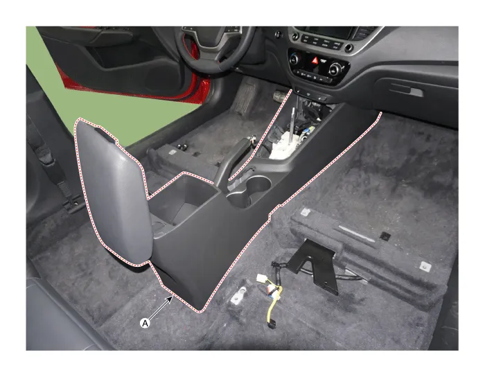
11.After loosening the mounting screws and bolts, remove the console rear complete assembly (A).
12.To install, reverse the removal procedure.

• Make sure the connector is connected properly.
• Replace any damaged clips (or pin - type retainers).

• Put on gloves to prevent hand injuries.

• When removing with a flat-tip screwdriver or remover, wrap protective tape around the tools to prevent damage to components.
• Use a plastic panel removal tool to remove interior trim pieces without marring the surface.
• Take care not to bend or scratch the trim and panels.
1.To remove the gear knob & gear boots (A) pull both of it up.
2.Remove the console front tray mat (A).
3.Using a screwdriver or remover, remove the console upper cover (A).
4.Disconnect the connector (A).
5.Remove the floor console front bezel (A) by pulling it rearward.
6.Disconnect the connectors (A).
7.Using a screwdriver or remover, remove the parking brake cover (A).
8.Remove the rear console tray mat (A).
9.Remove the consol7e rear mounting hole cap (A).
10.After loosening the mounting screws and bolts, remove the console complete assembly (A).
11.To install, reverse removal procedure.

• Make sure the connector is connected properly.
• Replace any damaged clips (or pin - type retainers).
Rear Console Cover
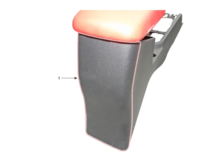
1. Rear console cover

• Put on gloves to prevent hand injuries.

• When removing with a flat - tip screwdriver or remover, wrap protective tape around the tools to prevent damage to components.
• Use a plastic panel removal tool to remove interior trim pieces without marring the surface.
• Take care not to bend or scratch the trim and panels.
1.Remove the floor console assembly.(Refer to Floor Console - "Floor Console Assembly")
2.Loosen the rear console mounting screws.
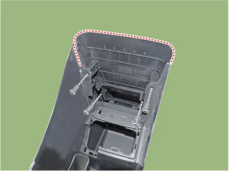
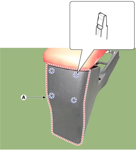
3.Using a screwdriver or remover, remove the rear console cover (A).
4.To install, reverse the removal procedure.

• Make sure the connector is connected properly.
• Replace any damaged clips (or pin - type retainers).
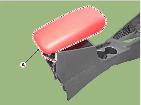
Console Armrest
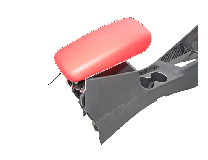
1. Console armrest

• Put on gloves to prevent hand injuries.

• When removing with a flat - tip screwdriver or remover, wrap protective tape around the tools to prevent damage to components.
• Use a plastic panel removal tool to remove interior trim pieces without marring the surface.
• Take care not to bend or scratch the trim and panels.
1.Remove the floor console assembly.(Refer to Floor Console - "Floor Console Assembly")
2.Remove the rear console cover.(Refer to Floor Console - "Rear Console Cover")
3.Loosen the mounting screws and remove the console armrest (A).
4.To install, reverse the removal procedure.

• Replace any damaged clips (or pin - type retainers).


Other information:
Hyundai Accent (HC) (2017 - 2022) Service Manual: Changing Tires
WARNING A vehicle can slip or roll off of a jack causing serious injury or death to you or those nearby. Take the following safety precautions: Never place any portion of your body under a vehicle that is supported by a jack. Your Hyundai Accent must be supported only at the correct jacking points and must never be relied on as a “stand.” NEVER attempt to change a tire in the lane of traffic.
Contents
Categories
- Manuals Home
- Hyundai Accent Owners Manual
- Hyundai Accent Service Manual
- Questions & Answers
- Video Guides
- Useful Resources
- New on site
- Most important about car
- Privacy Policy

0.0075