Hyundai Accent (HC): Ignition System / Ignition Coil
Hyundai Accent (HC) (2017 - 2022) Service Manual / Engine Electrical System / Ignition System / Ignition Coil
| Item | Specification |
| Rated Voltage (V) | 13.5 |
| Operation Voltage (V) | 6 - 16 |
| Item | Specification | |||||
| Engine Speed (RPM) | 1000 | 2000 | 3000 | 4000 | 5000 | 6000 |
| Dwell Time (ms) | 3.4 | 3.4 | 3.4 | 2.9 | 2.7 | 2.5 |
| Secondary Coil Voltage (kV) | 40 ↑ | 40 ↑ | 40 ↑ | 40 ↑ | 40 ↑ | 38 ↑ |
1.Remove the connector (A) and reinstall it.
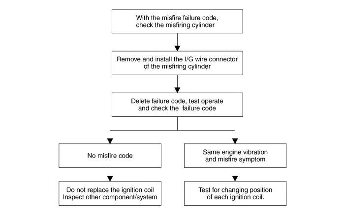

• Do not move with spark plug at the same time (move the ignition coil only)
1.Turn ignition switch OFF and disconnect the battery negative (-) terminal.
2.Remove the engine cover.
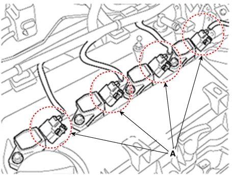
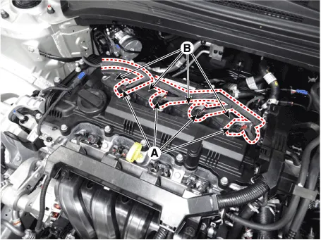
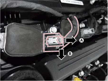
3.Disconnect the ignition coil connectors (A).
4.Remove the ignition coil after loosening the mounting bolts (B).
Ignition coil mounting bolt :9.8 - 11.8 N.m (1.0 - 1.2 kgf.m, 7.2 - 8.7 Ib-ft)
5.Install in the reverse order of removal.

• When removing the ignition coil connector, pull the lock pin (A) and push the clip (B).


Other information:
Hyundai Accent (HC) (2017 - 2022) Service Manual: Stop Lamp Switch
- Components 1. Brake pedal member assembly2. Stop lamp switch3. Brake pedal arm 4. Pedal pad - Schematic Diagram - System circuit diagram - Terminal function TerminalDescription 1IGN 2BS 3- 4B+ 5BLS 6GND - Adjustment 1.Turn ignition switch OFF and disconnect the negative (-) battery cable. 2.Remove the lower crash pad.Hyundai Accent (HC) (2017 - 2022) Service Manual: Description and Operation
- Function NoItemDescription 1Washer Linked Wiper – If the washer switch is pressed ON for 0.06 second with the vehicle mode in IGN2, the wiper relay is turned ON after washer switch ON, and then the wiper relay is turned OFF after wiper parking signal ON. 2MIST Linked Wiper – If the wiper mist switch is pressed ON for 0.6 second with the vehicle mode in IGN2, the wiper relay is turned ON, and then OFF after wiper parking signal ON.
Categories
- Manuals Home
- Hyundai Accent Owners Manual
- Hyundai Accent Service Manual
- Questions & Answers
- Video Guides
- Useful Resources
- New on site
- Most important about car
- Privacy Policy

Copyright © 2025
0.0053
0.0053