Hyundai Accent (HC): Driveshaft and axle / Driveshaft Assembly
Contents:
Front Driveshaft
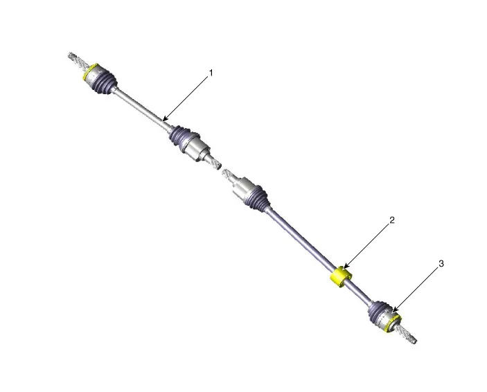
1. Driveshaft LH
2. Dynamic damper
3. Driveshaft RH
1.Loosen the wheel nuts slightly.Raise the vehicle, and make sure it is securely supported.
2.Remove the front wheel and tire (A) from the front hub.
Tightening torque :107.9 - 127.5 N.m (11.0 - 13.0 kgf.m, 79.6 - 94.0 lb-ft)
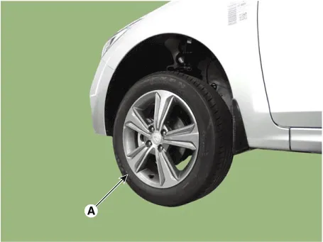

• Be careful not to damage the hub bolts when removing the front wheel and tire.
3.Loosen the driveshaft caulking nut (A).
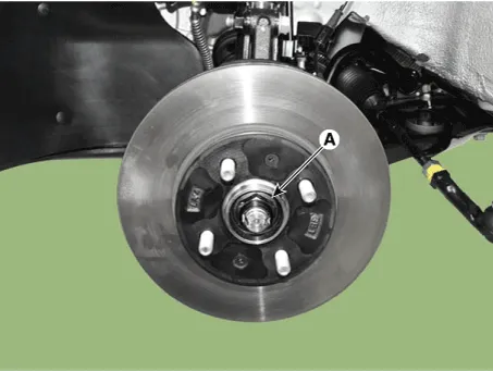

• The driveshaft lock nut (A) should be replaced with new ones.
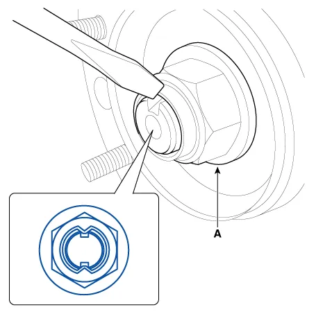
• After installation driveshaft lock nut, stake the lock nut using a chisel and hammer as shown in the illustration below.
Caulking depth : 1.5 mm (0.591 in.)
4.Remove the front brake caliper.(Refer to Brake System - "Front Disc Brake")
5.Remove the tie rod end ball joint.
(1)Remove the split pin (C).
(2)Loosen the nut (B).
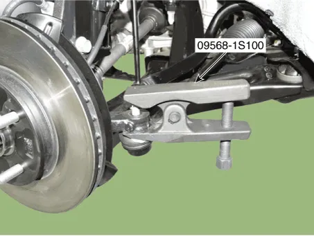
(3)Using SST(09568-1S100), separate the ball joint (A) from the knuckle.
Tightening torque :24.5-34.3 N.m (2.5 - 3.5 kgf.m, 18.1 - 25.3 lb-ft)
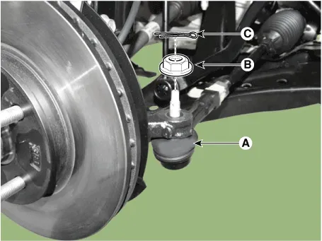

• Do not reuse the split pin (C).
6.Loosen the lower arm nut (A) and then remove the lower arm ball joint by using SST(09568-1S100).
Tightening torque : 58.8 - 70.6 N.m (6.0 - 7.2 kgf.m, 43.4 - 52.1 lb-ft)
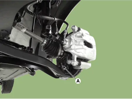
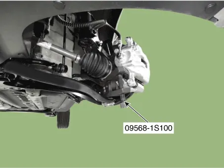

• Do not reuse the lower arm lock nut (A).
• Be careful not to damage the ball joint boots.
7.Using a plastic hammer, remove the front driveshaft (A) from the hub bearing assembly (B).
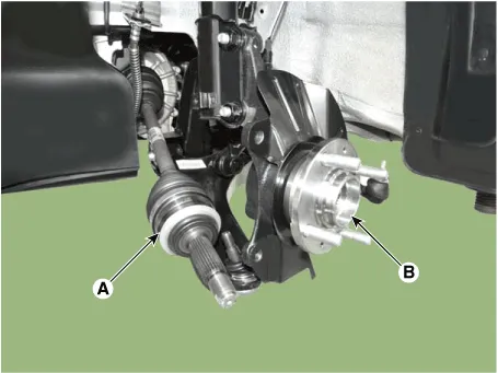

• Be careful not to damage the driveshaft, front sub frame or stabilizer link.
8.Insert a pry bar between the transaxle case and joint case, and separate the driveshaft from the transaxle case.
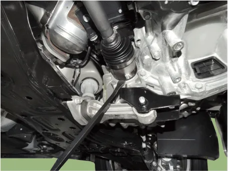
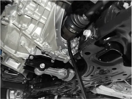

• Use a pry bar (A) being careful not to damage the transaxle and joint.
• Do not insert the pry bar (A) too deep, as this may cause damage to the oil seal.
• Do not pull the driveshaft by excessive force it may cause components inside the joint kit to dislodge resulting in a torn boot or a damaged bearing.
• Plug the hole of the transaxle case with the oil seal cap to prevent contamination.
• Support the driveshaft properly.
• Replace the retainer ring whenever the driveshaft is removed from the transaxle case.
9.Install in the reverse order of removal.
Dynamic Damper

1. BJ assembly
2. BJ circlip
3. BJ boot band
4. BJ boot
5. Dynamic damper band
6. Dynamic damper
7. Shaft
8. TJ boot band
9. TJ boot
10. Spider assembly
11. Snap ring
12. TJ housing
13. Clip
1.Remove the front driveshaft. (Refer to Driveshaft Assembly - "Front Driveshaft")
2.Remove the TJ joint assembly. (Refer to Driveshaft Assembly - "TJ Joint")
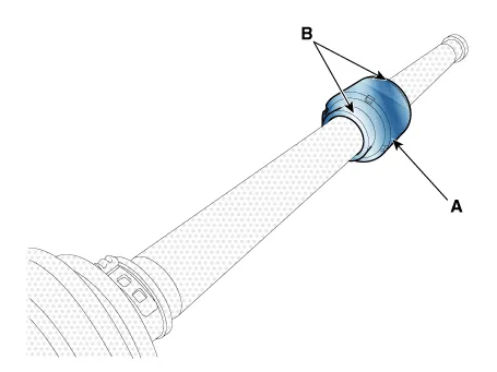
3.Remove the remove the both side of band (B) of the dynamic damper (A).
4.Fix the driveshaft (A) with a vice (B) as illustrated.
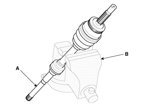
5.Apply soap powder on the shaft to prevent being damaged between the shaft spline and the dynamic damper when the dynamic damper is removed.
6.Seperate the dynamic damper (A) from the shaft (B) carefully.
1.Apply soap powder on the shaft to prevent being damaged between the shaft spline and the dynamic damper.
2.Install the dynamic damper.
3.Install the dynamic damper band.
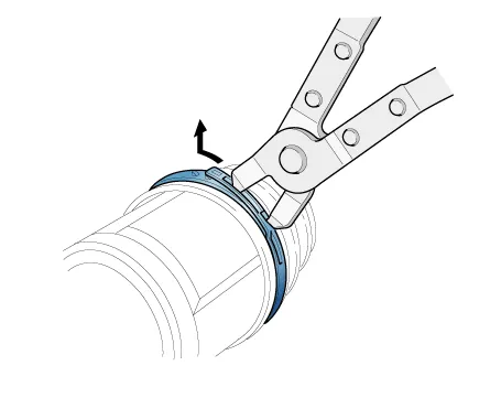
4.Using the pliers, secure the TJ boot bands.
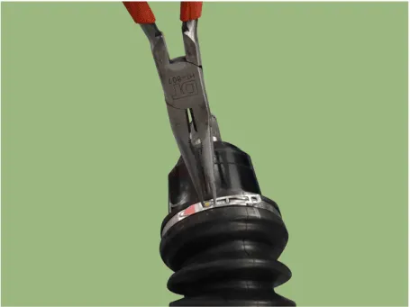

• Do not reuse the boot band.
5.Install the TJ joint assembly. (Refer to Driveshaft Assembly - "TJ joint")
6.Install the front driveshaft. (Refer to Driveshaft Assembly - "Front Driveshaft")
7.Check the front alignment.(Refer to Suspension System - "Front Alignment")
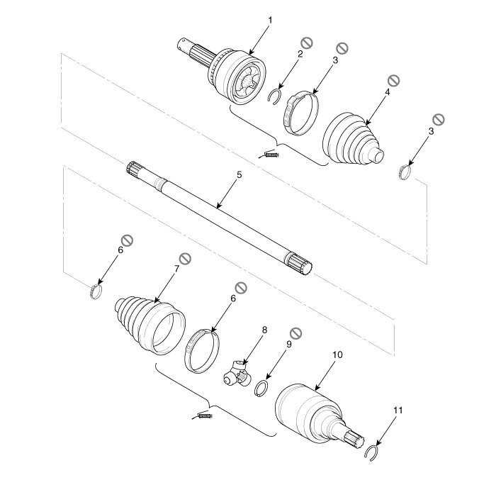
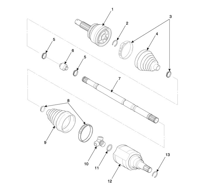
TJ Joint
[RH]

1. BJ assembly
2. BJ circlip
3. BJ boot band
4. BJ boot
5. Dynamic damper band
6. Dynamic damper
7. Shaft
8. TJ boot band
9. TJ boot
10. Spider assembly
11. Snap ring
12. TJ case
13. Clip
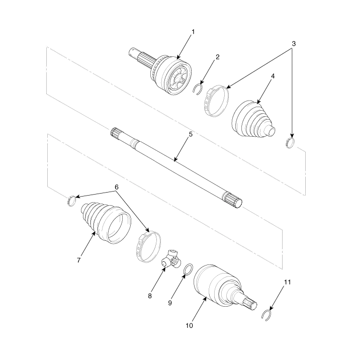
[LH]
1. BJ assembly
2. Circlip
3. BJ boot band
4. BJ boot
5. Shaft
6. TJ boot band
7. TJ boot
8. Spider assembly
9. Snap ring
10. TJ Case
11. Clip

• Special grease must be applied to the driveshaft joint. Do not substitute with another type of grease.
• The boot band should be replaced with a new one.
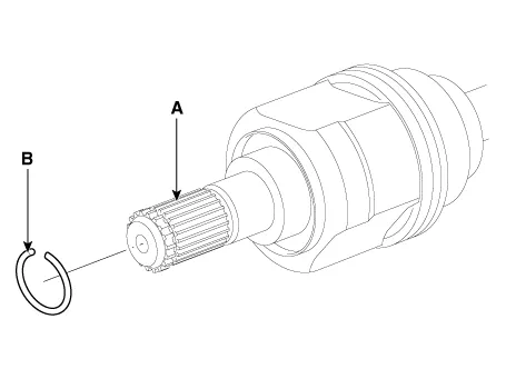
1.Remove the Front Driveshaft. (Refer to Driveshaft Assembly - "Front Driveshaft")
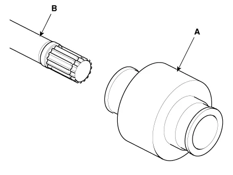
2.Remove the housing circlip (B) from the driveshaft spline (A).
3.Remove both boot bands from the TJ housing.
4.Remove the TJ housing (A).
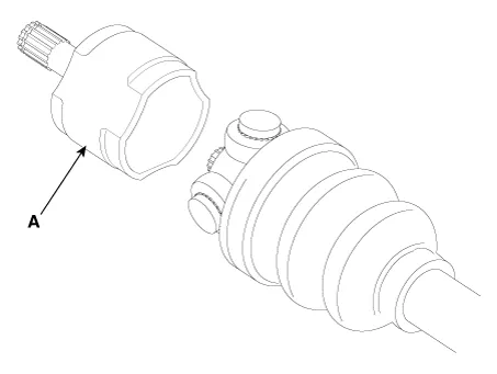

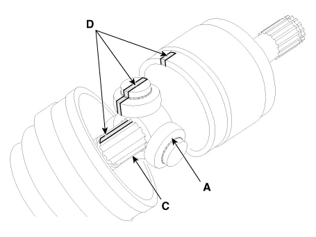
• Make alignment marks on spider roller assembly (A), joint case (B), and shaft spline (C) to aid reassembly.
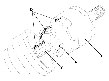
5.Remove the snap ring (A) from the shaft.

6.Remove the spider assembly (B) from the driveshaft (A) using the special tool SST (09495-3K000).


7.Clean the spider assembly.
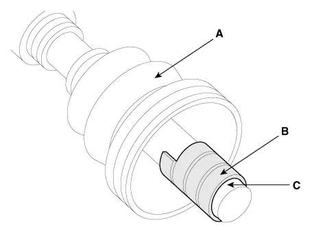
8.Remove the TJ boot (A).

• For reusing the boot (A), wrap tape (B) around the driveshaft splines (C) to protect the boot (A).
1.Check the driveshaft boots for damage and deterioration.
2.Check the driveshaft spline for wear or damage.
3.Check that there is no water or foreign material in the joint.
4.Check the spider assembly for roller rotation, wear or corrosion.
5.Check the groove inside the joint case for wear or corrosion.
6.Check the dynamic damper for damage or cracks.
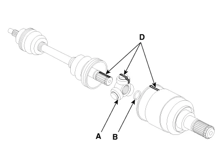
1.Wrap tape around the driveshaft spline(TJ) to prevent damage to the boot.
2.Using the alignment marks (D) made during disassembly as a guide, install the spider assembly (A) and snap ring (B) on the driveshaft splines (C).
3.Add specified grease to the joint boot as much as it was wiped away at inspection.
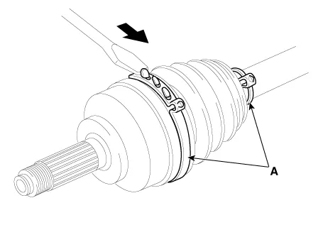
4.Install the both boot band.
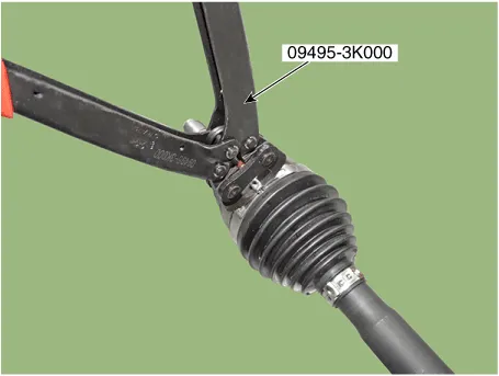
5.Using the SST (09495-3K000), secure the TJ boot bands.


• Do not reuse the boot band.
6.Install the front driveshaft. (Refer to Driveshaft Assembly - "Front Driveshaft")
7.Check the front alignment.(Refer to Suspension System - "Front Alignment")
BJ Boot
[RH]
1. BJ assembly
2. BJ circlip
3. BJ boot band
4. BJ boot
5. Dynamic damper band
6. Dynamic damper
7. Shaft
8. TJ boot band
9. TJ boot
10. Spider assembly
11. Snap ring
12. TJ housing
13. Clip
[LH]
1. BJ assembly
2. Circlip
3. BJ boot band
4. BJ boot
5. Shaft
6. TJ boot band
7. TJ boot
8. Spider assembly
9. Snap ring
10. TJ Case
11. Clip
1.Remove the front driveshaft. (Refer to Driveshaft Assembly - "Front Driveshaft")
2. Remove the TJ joint assembly. (Refer to Driveshaft Assembly - "TJ Joint")
3.Remove the Dynamic damper. (Refer to Driveshaft Assembly - "Dynamic Damper")
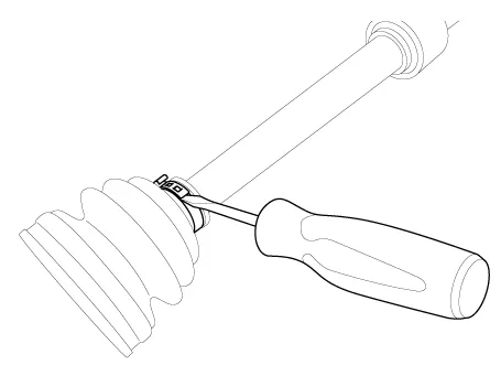
4.Using a plier or flat-tipped (-) screwdriver, remove the BJ boot bands (A).
5.Remove the BJ boot.
6.Install in the reverse order of removal.

• Do not disassemble the BJ assembly.
• Special grease must be applied to the driveshaft joint. Do not substitute with another type of grease.
• The boot band should be replaced with a new one.
7.Check the front alignment.(Refer to Suspension System - "Front Alignment")
1.To install, reverse the removal procedure.
2.Using the SST(09495-3K000), secure the BJ boot bands.


• Do not reuse the boot band.
3.Install the TJ joint assembly. (Refer to Driveshaft Assembly - "TJ joint")
4.Install the front driveshaft. (Refer to Driveshaft Assembly - "Front Driveshaft")
5.Check the front alignment.(Refer to Suspension System - "Front Alignment")


Other information:
Hyundai Accent (HC) (2017 - 2022) Service Manual: Repair procedures
- Removal 1.Remove the air cleaner assembly.(Refer to Engine Mechanical System - "Air cleaner") 2.Remove the battery and battery tray.(Refer to Body Electrical System - "Battery") 3.Drain the coolant.(Refer to Engine Mechanical System - "Coolant") 4.Disconnect the position switch connector (A). 5.Disconnect the driven pully speed sensor connector (B).Hyundai Accent (HC) (2017 - 2022) Service Manual: Seat Belt Restraint System
In the Hyundai Accent, the seat belt restraint system is designed to hold occupants in the correct position during everyday driving and to help reduce injury risk in a sudden stop or collision. For the best protection, always wear your seat belt correctly and confirm every passenger is properly buckled up before the Hyundai Accent starts moving. WARNING Improperly positioned seat belts may increase the risk of serious injury in an accident.
Contents
Categories
- Manuals Home
- Hyundai Accent Owners Manual
- Hyundai Accent Service Manual
- Questions & Answers
- Video Guides
- Useful Resources
- New on site
- Most important about car
- Privacy Policy

0.0082